From the preceding section, we saw that we can create a multiplexed display by switching on the individual digits one at a time. We can of course, use the MicroStamp11 to directly drive the common anode of the LED's, but this is a dangerous solution. Remember that we've designed the LED circuit so it draws a large current. This means that if we were to directly drive the LED's from the MicroStamp11, then we would probably draw more current than the MicroStamp11 could safely source. In other words, we would probably destroy the MicroStamp11. So we need to find a way of controlling the switching process without actually using the MicroStamp11 to drive the LEDs. This can be done through a simple transistor switch.
In particular, we may use a 2N4401 general purpose transistor as a switch. A transistor is a three-terminal semiconductor device that can be used as either an amplifier or switch. The operational amplifier you used earlier is a very complex transistor circuit that has been specially designed to provide the high gain, high input resistance, and low output resistance that characterize an op-amp. Transistors also can be used as electronic switches. Such switches lie at the heart of all digital logic circuits such as the simple shift-register you used earlier as well as the MicroStamp11 itself. These multiples uses of the transistor make it one of the most significant technological developments of the 20th century. Its invention effectively enabled the information age that marked the beginning of the new millennium.
A transistor has three terminals. The earliest transistor
technologies were based on creating a sandwich of ![]() and
and
![]() -type semi-conductor materials. These so-called
-type semi-conductor materials. These so-called ![]() or
or
![]() bipolar junction transistors (BJT)'s are still used
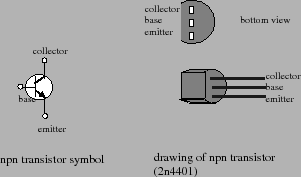
today. The 2N4401 is a BJT. The lefthand drawing in
figure 2 shows the electronic symbol
used for an
bipolar junction transistors (BJT)'s are still used
today. The 2N4401 is a BJT. The lefthand drawing in
figure 2 shows the electronic symbol
used for an ![]() BJT. From this figure you will see that
the three terminals for the transistor are referred to as
the collector, emitter, and base
terminals. The physical device is extremely small. It is a
small cylinder that has one side flattened. The flattened
side is used to help determine which of the three leads is
the base, emitter, and collector. A drawing of the
physical device is shown on the righthand side of figure
2.
BJT. From this figure you will see that
the three terminals for the transistor are referred to as
the collector, emitter, and base
terminals. The physical device is extremely small. It is a
small cylinder that has one side flattened. The flattened
side is used to help determine which of the three leads is
the base, emitter, and collector. A drawing of the
physical device is shown on the righthand side of figure
2.
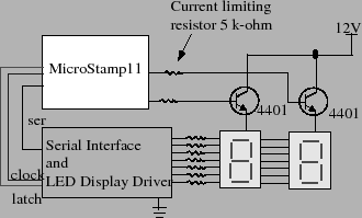
Transistors can be connected in a way that allows a relatively small base current to either switch on or off a relatively large collector current. Such a connection is shown in figure 3. In this figure, a 5 k-ohm resistor is connected in series to the base terminal of the transistor. The collector terminal is connected to the positive supply voltage of +9 volts and the emitter terminal is connected to the common anode of the 7-segment LED display. When the voltage level on the base terminal is low, then, the transistor switch is closed and a current flows from the nine volt supply, through the LED to ground. When the voltage level on the base terminal is high, then the switch is open and no current flows through the LED. The size of the emitter-collector current is controlled by the 100 ohm resistors of the LED driver circuit you designed in the last lab. Because of the small size of these resistors, the emitter-collector current is large when the transistor switch is closed and the LED's are bright. The base-emitter current is determined by the relatively large resistor (5 k-ohm) on the base terminal. Because of the large size of this resistor, the base-emitter current can be kept to low levels that can be tolerated by the MicroStamp11.