When we look at something like a circuit, we characterize
its behavior by determining the node voltages and branch
currents. But if these voltages and currents are
time-varying, then we can no longer use a single "number"
to characterize the circuit's behavior, we must use a
"function" that we'll refer to as a "signal". We define a
signal as a function that maps time onto some
real number. So, for instance, the voltage function ![]() is
a rule that associates a time
is
a rule that associates a time ![]() with an actual voltage
measurement
with an actual voltage
measurement ![]() . The value that
. The value that ![]() takes at a time
takes at a time ![]() is denoted as
is denoted as ![]() . Since both time and voltage are real
numbers, we can denote the voltage function using the
notation
. Since both time and voltage are real
numbers, we can denote the voltage function using the
notation
![]() . This notation says that
. This notation says that
![]() maps the real line back into itself.
maps the real line back into itself.
We say a signal, ![]() is periodic if there exists a
positive time
is periodic if there exists a
positive time ![]() such that
such that ![]() for all
for all ![]() . In other words, at any moment,
. In other words, at any moment, ![]() , in time, the
value of
, in time, the
value of ![]() (
(![]() ) will always be repeated some
specified time interval
) will always be repeated some
specified time interval ![]() in the future. We refer to
in the future. We refer to ![]() as the period of the signal. If
as the period of the signal. If ![]() is the smallest
positive number such that
is the smallest
positive number such that ![]() (for all
(for all ![]() ), then we refer to
), then we refer to ![]() as the signal's
fundamental period. If
as the signal's
fundamental period. If ![]() is the period of a periodic
signal
is the period of a periodic
signal ![]() , we often refer to
, we often refer to ![]() as being
as being ![]() -periodic.
-periodic.
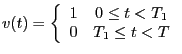
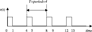
A pulse-width modulated signal is a ![]() -periodic
signal,
-periodic
signal, ![]() , if there exists
, if there exists ![]() such that
such that
This lab asks you to modify one of the output compare event
interrupt handlers in the kernel so that pin PA4 generates
a PWM signal whose duty cycle can be set from within the
main program. In order to complete this lab you
need to learn what an output compare event is and what an
interrupt handler is.