The waveform generated by your PWM signal generator is a time-varying waveform. To verify the functionality of your PWM signal generator, you must be able to plot the signal's voltage level as a function of time. A digital multi-meter (DMM) cannot be used to do this, you need another piece of electronic test equipment that is called on oscilloscope.
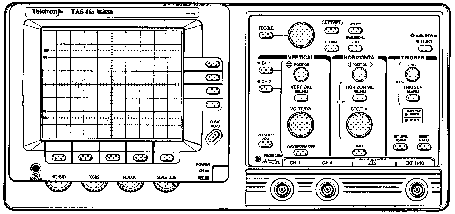
An oscilloscope is an instrument that provides a plot for a time-varying input signal. This lab uses a Tektronix analog scope. The control panel of this scope is shown in figure 4
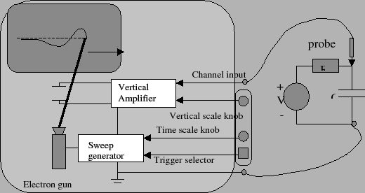
An analog oscilloscope consists of a cathode ray tube (CRT), sweep generator and a vertical amplifier as shown in figure 5. The sweep generator causes an electron beam in the CRT to sweep horizontally across a phosphorescent screen. The vertical amplifier moves the beam in a vertical direction in response to an applied input signal. The horizontal and vertical movement of the electron beam traces out the input signal's time variations. This trace appears on the oscilloscope's screen.
Figure 5 shows the internal components of the oscilloscope as well as the front panel of the Tektronix scope that you'll probably be using. Note that there are essentially three important types of controls that you need to be able to use. These controls are the
Unfortunately, CRT's are not like a piece of paper. When you write on the screen, the phosphor will emit light for only a short time. The picture, therefore, must be constantly refreshed. You have absolutely no hope of this happening unless the waveform you are trying to look at is constantly repeating (we refer to such waveforms as being periodic). Many interesting waveforms are periodic. With a repeating waveform you have some hope that the same image will be continuously refreshed so that your slow eyes can perceive it.
The earliest scopes had a knob that would let you adjust the sweep frequency in an attempt to match the frequency of the input signal. As you might guess, this made using a scope rather tricky. Fortunately, a much better system soon emerged, called the triggered sweep.
The idea behind a triggered sweep was to try to get the multiple sweeps to start at the same place in the waveform each time. This way the pictures would all line up. When the scope sees the input go past a certain level, it would trigger the horizontal sweep. Soon after a sweep was complete, the circuit would re-arm and await another trigger event.
This system, of course, had limitations. Complex waveforms, for example, that have multiple waves in a single period can easily confuse the trigger circuit. To trigger the circuit, all of the crossings of the trigger point will look the same so it will choose them randomly. Often there is another signal somewhere in the circuit with the same period, but without the extra bumps. Most scope will allow you to trigger the sweep for one channel from a different channel so you can synchronize to the cleaner signal.
The trigger is characterized by at least three parameters. These parameters are
About fifteen years ago,the next big advance in oscilloscope technology occurred. This advance was the digital scope. A digital storage oscilloscope (DSO) is basically a computer optimized for data acquisition. At the heart of a DSO is one or more high speed analog-to-digital converters. These ADC sample analog voltages and display them on a computer screen. Digital scope can do many things that analog scope cannot do. First of all the digital scope digitizes the wave form and can hold it on the screen forever. So you can take a snapshot of a particular signal and then study it at your leisure.
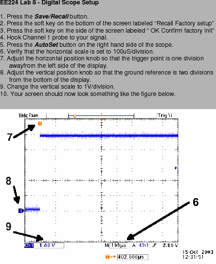
The initial set-up for a digital scope can be intimidating to the beginning student because the control panel looks so complicated. A set-up procedure for the scope has been provided below (see figure 6) If you follow this set-up you should be able to set-up the scope properly.
What you've just read is a rather hasty introduction to oscilloscopes, but this should be enough to get you started. In this lab, you'll need to use the oscilloscopes to capture PWM signal generated by your system. You will need to use the captured trace to measure the duty cycle and period of the PWM signal.