Research of homogeneous (single node and edge type) biological networks (BNs) has received significant attention. Graphlets have been proven in homogeneous BN research. Given the availability of BNs of different types (Figure 1), we generalize homogeneous graphlets to their heterogeneous counterparts, which encompass different node or edge types (Figure 2) and thus allow for analyzing a heterogeneous "network of networks" (Figure 1). We illustrate the usefulness of heterogeneous graphlets in the context of network alignment (NA). While existing NA methods are homogeneous (they account for a single node and edge type), we generalize three state-of-the-art homogeneous graphlet-based NA methods, WAVE, MAGNA++, and SANA, into their heterogeneous counterparts. Because graphlets are applicable to many network science problems, we provide an intuitive implementation (graphical user interface - GUI) and source code of our heterogeneous graphlet counting approach. Also, we provide code for our heterogeneous versions of the three NA methods. For detailed description and usage instructions, see below.
Reference: Shawn Gu, John Johnson, Fazle E. Faisal, and Tijana Milenkovic (2018), From homogeneous to heterogeneous network alignment, under review. Also, arXiv:1704.01221 [q-bio.MN].

Figure 1. Illustration of a heterogeneous network of networks

Figure 2. Illustration of node- and edge-colored graphlets.
The source code can be downloaded here. Our README file describes how to compile for each of Linux, Windows, and Mac OS X.
The GUI can be run by executing the "gui.exe" (Windows) or "gui" (macOS or Linux) file. The GUI contains the options to count any one or both of node- and edge-colored graphlets.
Linux 64-bit: download
Windows 64-bit: download
Windows 32-bit: download
Mac OS X: download
Example input and output files can be downloaded here. The input should be the network of interest and colors of nodes/edges in the network, and the output will be a file containing, for each node, the given node's node/edge-colored graphlet degree vector (GDV), which counts how many times the given node touches each of the node/edge-colored graphlets at each of the automorphism orbits. The notion of the node/edge-colored GDV of a node is an extension of the existing notion of the homogeneous GDV of a node, except that the former accounts for node/edge colors, while the latter does not.
Note: since graphlet counting is typically time-consuming, we suggest it to be done on a Linux server rather than on a personal Windows- or Mac OS X-based computer. This is exactly why we provide a command-line interface for our heterogeneous graphlet counting software.
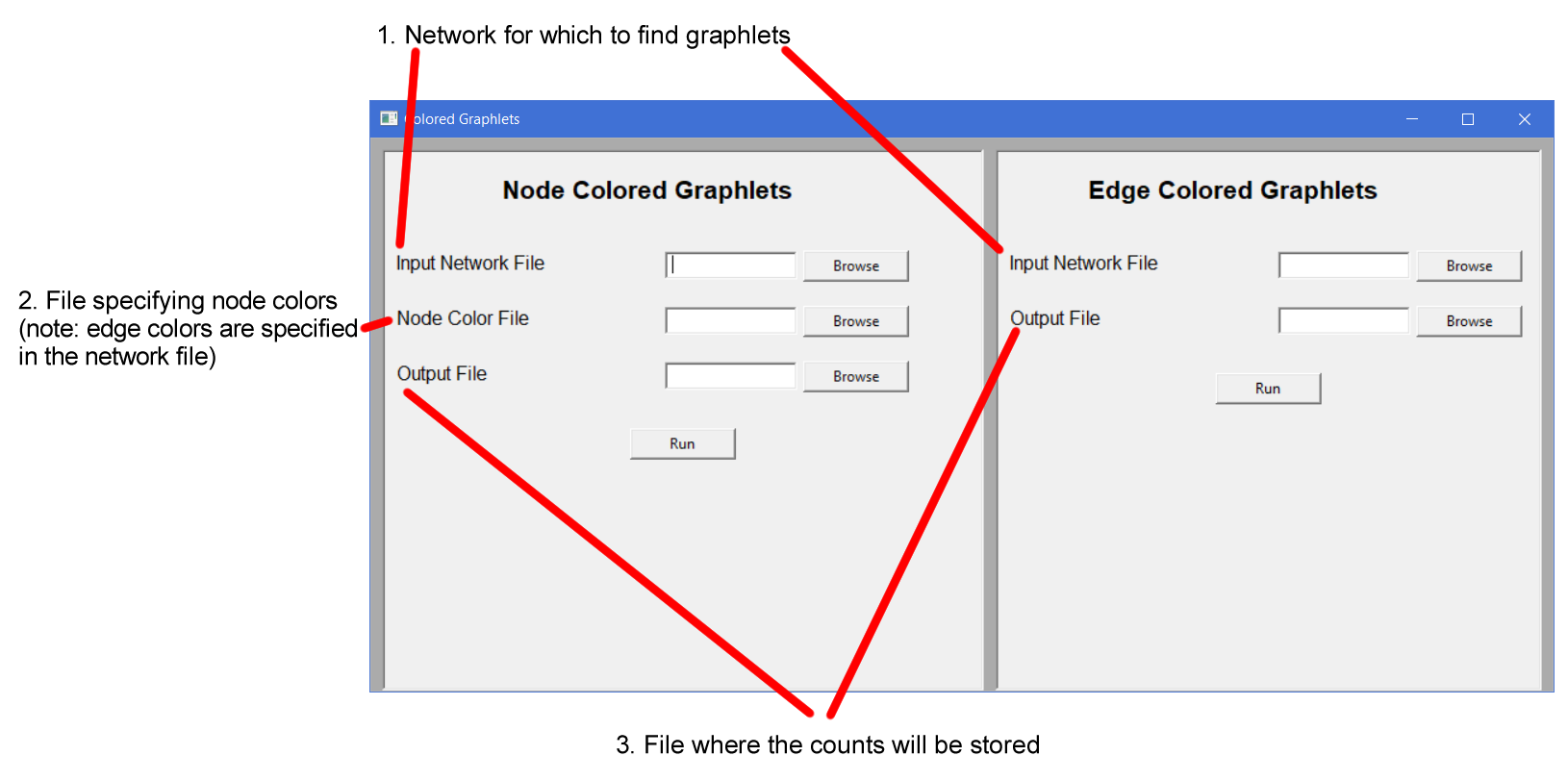
The specifications for the input files for GUI are the same as those for command line interface (see below).
$ ./colored-gdv_main -node [colored network file gw] [node color file] [output file]
$ colored-gdv_main.exe -node [colored network file gw] [node color file] [output file]
The network file should be in the standard gw format (that LEDA uses; one can use GraphCrunch's list2leda script to convert from the edge adjacency list format to the gw format). Edge weights (e.g., "0" in "1 2 0 |{1}|" below) or edge names (e.g., "|{1}|" in "1 2 0 |{1}|" below), if any, will be ignored by our counting program. An example file is shown below:
  EXAMPLE.GRAPH
  string
  int
  -1
  5
  |{v1}|
  |{v2}|
  |{v3}|
  |{v4}|
  |{v5}|
  10
  1 2 0 |{1}|
  2 3 0 |{2}|
  3 4 0 |{3}|
  4 1 0 |{4}|
  2 4 0 |{5}|
  5 3 0 |{6}|
  2 5 0 |{7}|
  4 5 0 |{8}|
  1 3 0 |{9}|
  1 5 0 |{10}|
The node color file should consist of two tab separated columns. The first column should have the node name as it is in the network file. The second column should have the node color. The colors must be integers, and they must be natural numbers starting at 1. An example file is shown below:
  v1  1
  v2  2
  v3  2
  v4  2
  v5  1
$ ./colored-gdv_main -edge [colored network file gw, which includes edge colors] [output file]
$ colored-gdv_main.exe -edge [colored network file gw, which includes edge colors] [output file]
The network file should be in the standard gw format (see above), except that the edge weights (e.g., "2" in "3 4 2 |{3}|" below) should be replaced by the edge colors. The colors must be integers, and they must be natural numbers starting at 1. An example file is shown below:
  EXAMPLE.GRAPH
  string
  int
  -1
  5
  |{v1}|
  |{v2}|
  |{v3}|
  |{v4}|
  |{v5}|
  10
  1 2 1 |{1}|
  2 3 2 |{2}|
  3 4 2 |{3}|
  4 1 1 |{3}|
  2 4 2 |{3}|
  5 3 1 |{3}|
  2 5 3 |{3}|
  4 5 3 |{3}|
  1 3 2 |{3}|
  1 5 1 |{3}|
Assume that we use the following network file as input:
  LEDA.GRAPH
  string
  int
  -1
  3
  |{v1}|
  |{v2}|
  |{v3}|
  3
  1 2 1 |{1}|
  2 3 2 |{2}|
  2 3 1 |{3}|
An example edge-colored output corresponding to the above input is shown below, where each row is the edge-colored GDV of the given node:
  v1 1 0 0 0 0 1 0 0 0 ...
  v2 1 0 1 0 0 0 0 0 1 ...
  v3 0 0 1 0 0 1 0 0 0 ...
For illustration, only the first nine orbits of the edge-colored GDV (see the paper for details) are shown. For example, v2 touches once the ninth orbit (i.e., orbit 8, since orbits are numbered starting from 0) of the edge-colored GDV.
This network has two edge colors (color 1 and color 2), so there will be three possible edge-colored graphlets for each homogeneous graphlet (corresponding to the following three color combinations: {1}, {2}, {1,2}). Note that we produce heterogeneous graphlets for all up to 5-node homogeneous graphlets, where the homogeneous graphlets and their orbits follow the standard nomenclature (see Figure 1 in this paper). Orbits 0-2 of the edge-colored GDV correspond to the first homogeneous graphlet orbit (homogeneous orbit 0 in Figure 1 in this paper, i.e., an edge), orbits 3-5 of the edge-colored GDV correspond to the second homogeneous orbit (homogeneous orbit 1 in Figure 1 in this paper, i.e., the outer nodes of a three node path), and orbits 6-8 correspond to the third homogeneous orbit (homogeneous orbit 2 in Figure 1 in this paper, i.e., the middle of a three node path). The same applies to all other orbits that are not shown. Details on how to map a heterogeneous orbit to a homogenous orbit and to a set of colors can be found in our README.
Given all possible 73 orbits for 2-5-node homogeneous graphlets, (numbered from 0 to 72 in Figure 1 in this paper), and given k node/edge colors, there will be 73(2k-1) orbits in the node/edge-colored GDV.
The data can be found here.
Code for homogeneous WAVE can be found here. See the README included in the .zip for usage details on how to combine this code with heterogeneous graphlet-based node similarity information in order to run our heterogeneous version of WAVE.
Code for our heterogeneous MAGNA++ can be found here. See the README included in the .zip for usage details.
Homogeneous SANA is not a method by our group, and it might have some intellectual property restrictions imposed by the original authors, which is why we cannot share any part of its code. So, we will only provide pseudocode for the relevant functions needed to convert the homogeneous SANA into its heterogeneous counterpart, as described below. So, a user can obtain the homogeneous SANA code from the original authors and implement changes as described in our pseudocode to get our heterogeneous version of SANA.
Let u and v be nodes in G.
Let u', v', and w' be nodes in H.
Let hasEdge(u, v) return true is an edge exists between u and v, and return false if an edge does not exst.
Let A be an alignment between G and H such that A[u] = u' and A[v] = v'.
Let numCons be the number of conserved edges and numNonCons be the number of non-conserved edges.
Let colorsG be a structure identifying the colors of the nodes in G (e.g., colorsG[u]).
Let colorsH be a structure identifying the colors of the nodes in H (e.g., colorsH[u']).

Try the alignment A[u] = u' and A[v] = w'
change(u, v, u', v', w', A, numCons, numNonCons, colorsG, colorsH):
  if hasEdge(u, v) and hasEdge(u', v'):
    if (colorsG[u] == colorsH[u']) and (colorsG[v] == colorsH[v']):
      numCons = numCons - 1
    else if (colorsG[u] != colorsH[u']) and (colorsG[v] != colorsH[v']):
      numCons = numCons - 0.33
    else if (colorsG[u] == colorsH[u']) or (colorsG[v] != colorsH[v']):
      numCons = numCons - 0.67
  else if hasEdge(u, v) or hasEdge(u', v'):
    numNonCons = numNonCons - 1


  if hasEdge(u, v) and hasEdge(u', w'):
    if (colorsG[u] == colorsH[u']) and (colorsG[v] == colorsH[w']):
      numCons = numCons + 1
    else if (colorsG[u] != colorsH[u']) and (colorsG[v] != colorsH[w']):
      numCons = numCons + 0.33
    else if (colorsG[u] == colorsH[u']) or (colorsG[v] != colorsH[w']):
      numCons = numCons + 0.67
  else if hasEdge(u, v) or hasEdge(u', w'):
    numNonCons = numNonCons + 1

  return numCons, numNonCons

Try the alignment A[u] = v' and A[v] = u'
swap(u, v, u', v', A, numCons, numNonCons, colorsG, colorsH):
  if hasEdge(u, v) and hasEdge(u', v'):
    if (colorsG[u] == colorsH[u']) and (colorsG[v] == colorsH[v']):
      numCons = numCons - 1
    else if (colorsG[u] != colorsH[u']) and (colorsG[v] != colorsH[v']):
      numCons = numCons - 0.33
    else if (colorsG[u] == colorsH[u']) or (colorsG[v] != colorsH[v']):
      numCons = numCons - 0.67

    if (colorsG[u] == colorsH[v']) and (colorsG[v] == colorsH[u']):
      numCons = numCons + 1
    else if (colorsG[u] != colorsH[v']) and (colorsG[v] != colorsH[u']):
      numCons = numCons + 0.33
    else if (colorsG[u] == colorsH[v']) or (colorsG[v] != colorsH[u']):
      numCons = numCons + 0.67

  else if hasEdge(u, v) or hasEdge(u', v'):
    numNonCons = numNonCons - 1
    numNonCons = numNonCons + 1       // there is no net effect in this case, but we leave the lines in to represent the swap

  return numCons, numNonCons