


Next: In-Lab Tasks:
Up: Tasks
Previous: Tasks
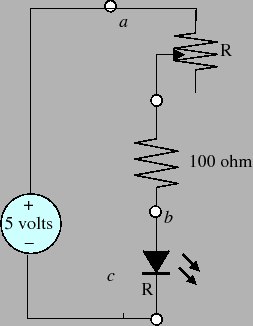
Consider the circuit shown in
figure 15. This circuit consists of a
5 volt independent voltage source driving a resistive
circuit with a single diode. One of the resistors is a 100
ohm resistor. The other resistor is a variable resistor
whose value can be changed between 0 and 10 kilo ohms.
Since the second resistor's value is variable, the second
resistor's value is denoted by the variable  .
.
Figure 15:
Circuit for Lab 1
 |
Before coming to the lab you should do the following:
- Draw a labelled schematic diagram of the
circuit with an explanation of how the circuit works.
- Draw a picture showing how you plan to breadboard
the circuit.
- Derive an expression for the current going through
the diode as a function of the variable resistance, .
- Plot the current through the LED as a function
of the variable resistance .
Ask the TA to check your completed pre-lab analysis. If
your answers are correct, then you can proceed to the
In-lab task.
Michael Lemmon
2009-02-01