Electrically charge particles exert a force on each other. The magnitude of this force is dependent on the charge on each particle. The magnitude of the force is inversely proportional to the square of the distance between particles.
The base unit of charge is the coulomb. One
coulomb equals the charge of
![]() electrons. In other words, a single electron has a charge
of
electrons. In other words, a single electron has a charge
of
![]() coulombs. The symbol for
charge is
coulombs. The symbol for
charge is ![]() or
or ![]() .
.
Electric circuits move electrical charge around so that
useful work is accomplished. These moving charges generate
an electric current that we denote as ![]() or
or ![]() . In
other words, if
. In
other words, if ![]() is the amount of charge at a
specific point in space at time
is the amount of charge at a
specific point in space at time ![]() , then the current
passing through this point equals the first time derivative
of
, then the current
passing through this point equals the first time derivative
of ![]() . In other words,
. In other words,
Consider a wire that has a current of ![]() amps passing
across a specific point on that wire. The charge can
either be moving from right to left or left to right. So
to completely specify the nature of the current, we must
also specify the direction in which the current is
travelling. This is done by associating a sign to
the current. In other words, current is a signed
quantity.
amps passing
across a specific point on that wire. The charge can
either be moving from right to left or left to right. So
to completely specify the nature of the current, we must
also specify the direction in which the current is
travelling. This is done by associating a sign to
the current. In other words, current is a signed
quantity.
The sign given to a current depends upon what we are interested in measuring. Moving charge can be thought of as either
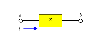
In circuit diagrams, we denote the current flowing into a circuit element by an arrow labelling one of the device's terminals. The arrow is usually labelled with the size of the current. The standard convention (called the passive labelling convention) used in labelling these arrows is to use a positive number when then current is pushing positive charges into the device. If the number is negative, then the current is pulling positive charges out of the device. Figure 16 illustrates the passive labelling convention for a resistor.
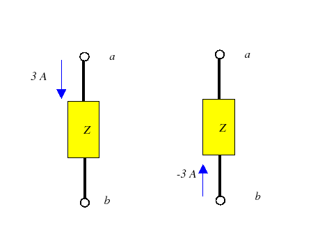
Recall that the number labelling the current is signed with
an arrow. This means we can obtain two different labels for
the same direction of conventional current. Figure
17 shows two such labels. In
the first case, we are pushing positive charge from
terminal ![]() into the device. In the second case, we are
pulling positive charge from the device into terminal
into the device. In the second case, we are
pulling positive charge from the device into terminal ![]() .
The end result for both labels is the same, namely that the
flow of positive charges is from left to right through the
device.
.
The end result for both labels is the same, namely that the
flow of positive charges is from left to right through the
device.
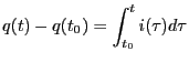
The total charge entering a circuit element is obtained by
integrating the differential equation ![]() .
Assume that the charge is initially
.
Assume that the charge is initially ![]() , then the
total charge entering the device between times
, then the
total charge entering the device between times ![]() and
and
![]() will be
will be
 |