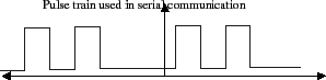
The serial communication protocols you used in the last project transmitted a series of voltage pulses down a wire. Each pulse represented a bit. When you attached an oscilloscope to this wire and triggered correctly, then the observed trace might have looked something like the trace in figure 1.
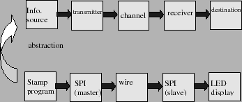
There are, however, other ways of transmitting information besides toggling between zero and 5 volts. If we had abstracted the communication systems you used earlier to extract their essential conceptual components, we would end up with a block diagram something like that found in figure 2. In this figure, we find an information source, whose information is transformed into a signal that can be transmitted through a physical channel. On the other end of the channel, the received signal is transformed back into information that can be directly used by the destination.
The abstracted blocks in figure 2 (source, transmitter, channel, receiver, and destination) all have concrete implementations in the system you built in lab 8. The information source was the MicroStamp11 program used to increment and decrement a desired integer. The channel consists of the wires between the micro-controller and the slave device. Finally, the destination was that two digit LED display you built.
The block diagram shown in figure 2 represents a high level abstraction of a concrete communication system. But given this abstraction, we can substitute lab 8's realization for these blocks by other concrete realizations and thereby obtain a different type of communication system. The different type of communication system we'll consider in this lab is a wireless communication system.