To complete this lab you'll need to find a way to detect
the start bit of a frame. The start bit is known to be of
duration ![]() . Since we know all other data bits are of
longer duration than this, we can reliably detect the
beginning of a frame by looking for a short pulse of
duration
. Since we know all other data bits are of
longer duration than this, we can reliably detect the
beginning of a frame by looking for a short pulse of
duration ![]() seconds. This means we will need to be able
to measure pulse widths. Pulse widths can be measured
using input capture interrupts. This section
discusses the use of input capture interrupts on the
MicroStamp11.
seconds. This means we will need to be able
to measure pulse widths. Pulse widths can be measured
using input capture interrupts. This section
discusses the use of input capture interrupts on the
MicroStamp11.
The input capture (IC) event is a hardware event tied to
the logical state of one of the input pins on PORTA. We
begin by connecting an external TTL level signal to pins
PA2, PA1, or PA0 on PORTA. Recall that these pins always
have the "input" direction state. Pins PA0, PA1, and P2
are tied to IC events IC3, IC2, and
IC1, respectively. If the logical voltage level on
one of these pins changes, then the MicroStamp11 latches
the current 16-bit value of the timer register TCNT
into the pin's input capture latch register. The
logical names for the latch registers associated with input
capture events IC1, IC2, and IC3 are
TIC1, TIC2, and TIC3, respectively.
We can have the input capture event trigger an input
capture interrupt if the input capture interrupt bit
(IC1I, IC2I, or IC3I) is set in the
control register TMSK1. So, for example, if we set
pin IC1I in TMSK1, then the occurrence of an
input capture event on pin PA2 will do two things.
First it will cause TCNT's current value to be
latched into register TIC1. Second, it will cause
the program to jump to the interrupt vector associated with
interrupt IC1. The first action essentially records
the time when the input capture event occurred. The second
action jumps to an ISR that performs the computations
required to service the IC1 interrupt.
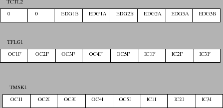
Figure 2 shows the three control
registers used by the input capture interrupts. These three
registers have the logical names TMSK1,
TFLG1, and TCTL2. The register TMSK1
is a control register that is used to "arm the input
capture interrupt. Arming the input capture interrupt
IC1, for instance, is accomplished by setting bit
IC1I in register TMSK1. The register
TFLG1 is a status register that can be used to
"acknowledge" the servicing of a caught interrupt. We
acknowledge a previously caught IC interrupt such as
IC1 by setting bit IC1F in register
TFLG1. The final register TCTL2 is used to
define the "way" in which an input capture event is
generated.
It is rather vague to say that the IC event occurs when the
input pin's logical state changes, for it is unclear what
we mean by a change of state. Does the voltage rising from
0 to 5 volts (a rising edge) or does the falling voltage
(from 5 to 0 volts) constitute a "change of state"? In
fact, we can identify three types of input capture events
based on how we define a state change. We can trigger an
event on the rising edge, the falling edge, or on either
rising/falling edges. Which edge we choose to use for
triggering the IC event can be specified by setting the
appropriate bits in the TCTL2 control register.
The bits in TCTL2 that define the edge events for
ICn (![]() or
or ![]() ) have the logical names
) have the logical names
EDGnB and EDGnA. The effect that setting
these bits have on defining the input capture event for the
![]() th pin is given in the following table:
th pin is given in the following table:
EDGnB |
EDGnA |
Active edge |
| 0 | 0 | none |
| 0 | 1 | capture on rising |
| 1 | 0 | capture on falling |
| 1 | 1 | capture on both rising and falling |
Input capture events can be used to measure the width of a
pulse. This is done by using an input capture event that
triggers on the rising edge of a pulse. The ISR servicing
this interrupt saves the time when the interrupt was
received and then resets the interrupt so it triggers on
the falling edge. When the IC interrupt is triggered the
next time, we can then subtract the time in TIC1
from the previously saved IC interrupt time to obtain the
duration of the pulse. The following code segment shows
how this might be done using the IC1 interrupt.
 unsigned int _start_pulse;
 unsigned int _pulse_width;

 #pragma interrupt_handler IC1han();
 void IC1han(void){
   asm(" sei");
   if(TCTL2 == 0x10){
     TCTL2 = 0x20;
     _start_pulse = TIC1;
     TFLG1 |= IC1;
   }else{
     if(_start_pulse < TIC1){
      _pulse_width = TIC1 - _pulse_width;
     }else{
      _pulse_width = 65536 - _start_pulse + TIC1;
     }
     TCTL2 = 0x10;
     TFLG1 |= IC1;
   }
 }

 extern void IC1han();
 #pragma abs_address:0xffee;
 void (* IC1_handler[])() = { IC1han };
 #pragma end_abs_address
The preceding ISR uses two globally declared variables,
_pulse_width and _start_pulse. In the
initialization routine init(), we would first arm
the IC1 interrupt by setting the appropriate bit in
register TMSK1. In this initialization routine we
would also use the instruction TCTL2 = 0x10 to
trigger IC1 interrupts on the rising edge of the received
pulse on pin PA2. The ISR first checks to see if
the interrupt was triggered by a rising edge or a falling
edge. If the interrupt was triggered by a rising edge,
then we reset TCTL2 = 0x20 to cause the next IC
interrupt to occur on a falling edge. We then store the
time TIC1 when the first IC1 interrupt occurred in
the global variable _start_pulse.
If the ISR is triggered on a falling edge, then we know
that _start_pulse already contains the time when the
rising edge of the pulse occurred. So all we need to do is
difference TIC1 from _start_pulse to get the
pulse width _pulse_width. This computation,
however, is complicated by the fact that TIC1 is the
value in a 16-bit counter TCNT. If this counter
overflows after _start_pulse, then it is possible
that TIC1 is actually less than _start_pulse.
So our ISR needs to check and see if an overflow occurred
by checking to see if TIC1 is greater than
_start_pulse. If this condition holds, then we
merely need to difference _start_pulse from
TIC1 to obtain _pulse_width. If an overflow
has occurred then TIC1 is less than
_start_pulse and we'll need to add 65536 to the
difference in order to get the correct value for
_pulse_duration.