Now that we've stepped down the AC voltages to a
level that is more in line with the voltage requirements of
the ![]() Stamp11, we are left with the problem of
converting a 12 volt AC signal into our desired 5 volt DC
power supply. We'll approach this in two steps. First
we'll convert the AC voltage into a DC voltage via a
process known as rectification. Then we'll step down
this 12 volt DC voltage down to 5 volts using the
voltage regulator . This section briefly talks about the
rectification process.
Stamp11, we are left with the problem of
converting a 12 volt AC signal into our desired 5 volt DC
power supply. We'll approach this in two steps. First
we'll convert the AC voltage into a DC voltage via a
process known as rectification. Then we'll step down
this 12 volt DC voltage down to 5 volts using the
voltage regulator . This section briefly talks about the
rectification process.
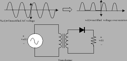
The simplest possible circuit for converting AC into DC is a half-wave rectifier. This circuit consists of a single diode that only allows current to flow in one direction. A possible circuit is shown below in figure 4. In this figure, you'll find the AC power source connected to the primary side of a transformer. Note the symbol we use for the transformer. The secondary terminals of this transformer are then connected to a diode and resistor in series.
The operation of this circuit is straightforward. When
![]() is in the positive part of its cycle, a positive
voltage is produced on the secondary side of the
transformer. This voltage forward biases the diode and the
diode begins passing current. As a result most of the
voltage drops across the load. When
is in the positive part of its cycle, a positive
voltage is produced on the secondary side of the
transformer. This voltage forward biases the diode and the
diode begins passing current. As a result most of the
voltage drops across the load. When ![]() is negative,
then the secondary side also has a negative voltage. The
diode is then reverse biased and ceases to pass current. As
a result, the voltage drop over the load is zero. The
voltage waveform over the load resistor therefore looks as
shown in figure 4. Only the positive side
of the sinusoidal cycle is present and the negative side
has been clamped off by the diode.
is negative,
then the secondary side also has a negative voltage. The
diode is then reverse biased and ceases to pass current. As
a result, the voltage drop over the load is zero. The
voltage waveform over the load resistor therefore looks as
shown in figure 4. Only the positive side
of the sinusoidal cycle is present and the negative side
has been clamped off by the diode.
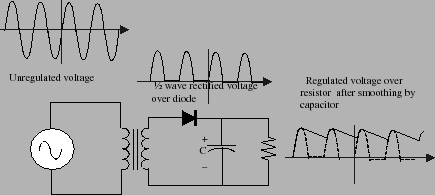
Looking at the output voltage,![]() , you should note
that it resembles the output of the battery in that it is
always positive. Unfortunately, this positive waveform is
rather "bumpy" and we need to find a way to smooth it out.
The RC
circuit shown in figure 5 is used to
smooth out these bumps. In this circuit, we've added a
large capacitor in parallel with the load resistance. The
capacitor can store energy during the times when the
voltage over the load is positive. When the load voltage
is clamped to zero, our capacitor can then slowly release
its stored energy, thereby smoothing out the voltage over
the load.
, you should note
that it resembles the output of the battery in that it is
always positive. Unfortunately, this positive waveform is
rather "bumpy" and we need to find a way to smooth it out.
The RC
circuit shown in figure 5 is used to
smooth out these bumps. In this circuit, we've added a
large capacitor in parallel with the load resistance. The
capacitor can store energy during the times when the
voltage over the load is positive. When the load voltage
is clamped to zero, our capacitor can then slowly release
its stored energy, thereby smoothing out the voltage over
the load.
What happens in this circuit is that the diode turns on when the voltage on the cap is about 0.7 volts (the threshold voltage for the diode) below that coming out of the transformer. Meanwhile the load discharges the cap with our standard RC time constant. The circuit must be carefully designed so that the time-constant is much longer than the AC cycle time. Even so, the cap will probably lose some voltage over the idle time between pulses and this loss will result in voltage ripple. The resulting waveforms are shown below in figure 5.
There is something else new in this circuit. Notice how
the bottom plate of the capacitor is shown with a curve and
the top plate is marked with a plus sign. This is because
special capacitors are required to get a high capacitance
in a small space. In particular, you'll be using
electrolytic capacitors. Such capacitors are constructed
using a paper soaked in an electrolyte. This fabrication
method gives enormous capacitances in a very small volume.
But it also results in the capacitor being polarized.
In other words, the capacitor only works with one polarity
of voltage. If you reverse the polarity, hydrogen can
disassociate from the internal anode of the capacitor and
this hydrogen can explode. Electrolytic capacitors always
have their polarity clearly marked, often with a bunch of
negative signs pointed at the negative terminal. You
should have a 1000 ![]() F capacitor in your parts kits that
you can use in your power supply circuit.
F capacitor in your parts kits that
you can use in your power supply circuit.
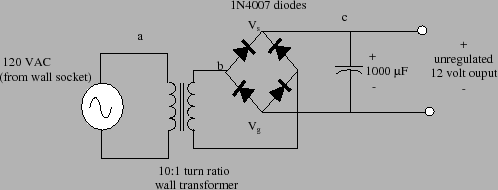
While the half-wave rectifier has the virtue of simplicity, it lacks efficiency because we are throwing away the negative side of the waveform. A better solution would be to use the power in both sides of the waveform. Circuits that do this are called full-wave rectifiers. In particular, you can use the following circuit shown in figure 6 to build the full-wave rectifier. The left-hand side of this circuit is the full wave bridge. This part of the circuit consists of four specially arranged diodes. The output of the full wave rectifier is is, essentially a 12 volt DC supply. There will be a small ripple on this supply, but you won't really be able to notice it even if you look at the waveform using the oscilloscope.
The circuit shown in figure 6 generates a DC
voltage of 12-volts and ground across the two terminals
marked ![]() and
and ![]() . Your MicroStamp11, however,
requires a 5 volt supply. We can step down this 12 voltage
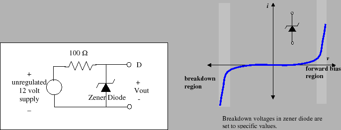
voltage to a 5 voltage voltage in several ways. One method
is to use a Zener diode to clamp the voltage at 5 volts. A
zener diode is a diode whose breakdown voltages has been
designed to sit at a specific voltage level. The circuit
shown in figure 7 performs this
function. The resistor in series with the diode is used to
limit the output current, typical values are on the order
of 100-500 ohms.
. Your MicroStamp11, however,
requires a 5 volt supply. We can step down this 12 voltage
voltage to a 5 voltage voltage in several ways. One method
is to use a Zener diode to clamp the voltage at 5 volts. A
zener diode is a diode whose breakdown voltages has been
designed to sit at a specific voltage level. The circuit
shown in figure 7 performs this
function. The resistor in series with the diode is used to
limit the output current, typical values are on the order
of 100-500 ohms.
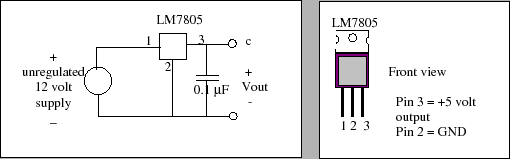
Another way of stepping down the 12 voltage supply is to use a special three-terminal device called a voltage regulator. A voltage regulator is a special semiconductor device that has been specially designed to act as an ideal battery. The voltage regulator connections are shown on the righthand side of figure 8. As you can see the voltage regulator has 3 pins. Pin 3 (VIN) is connected to the positive battery terminal. Pin 2 (GND) is connected to ground (the negative terminal of your battery) and Pin 1 is the 5 volt regulated output. In your lab kit you'll find an LM7805 voltage regulator. You can use this to construct the regulator driven power supply for your system.
In connecting your voltage regulator be sure to put a 0.1
![]() F capacitor on the output end of your power supply.
This capacitor helps remove voltage spikes from your power
supply, for if you have a step change in the voltage, the
capacitor acts as a short circuit to ground.
F capacitor on the output end of your power supply.
This capacitor helps remove voltage spikes from your power
supply, for if you have a step change in the voltage, the
capacitor acts as a short circuit to ground.