
Introduction

Introduction
Figure 1:Applications of Liquid Dampers
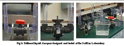
In order to adjust damping in the TLCD, two different types of valves are being investigated, namely, the ball valve and the butterfly valve shown below attached to the TLCD (Fig. 3). The valve supplier have provided the characteristic curves for orifice opening and the head-loss coefficient. A unique feature of the design is that these are true union valves, so one can take these off and fit a separate valve without disassembling the whole damper.
The controllable passive strategy ensures
that the damping is kept optimal at all levels of excitation for the TLCD.
This strategy utilizes a semi-active gain scheduling type lookup table
which can estimate the optimal coefficient of head-loss for a given level
of loading. This can then be changed in the valve based on feedback from
the sensors (Fig. 4(a)). The Semi-active control valve is shown in the
Fig. 4(b). This control valve is a pneumatically actuated ball/butterfly
valve with an additional solenoid valve for modulating the valve opening.
The electro-pneumatic positioner uses a 4-20mA signal to change the valve
position. The positioner modulates the flow of supply air and converts
the input signal to a 3-15 psi air signal for proportional modulation of
the valve. One of the advantages of these smart dampers is that even if
the electric valve fails for any reason, the system still functions at
some level of damping available for that valve setting.
Applications of liquid dampers
Most applications are described in a detailed paper by Kareem et al (1999)3. Structural implementation of TLDs on structures was first done in Japan. Examples of TLD-controlled structures include Nagasaki Airport tower, Yokohoma Marine Tower, Shin Yokohoma Prince Hotel and Tokyo international airport tower. (Fig. 5(b)). TLCDs have been implemented for Higashi-Kobe cable-stayed bridge to reduce wind-induced vibrations of the bridge towers (Fig 5(c)). A LCD-PA (liquid column damper with pressure adjustment) has been installed in the Hyatt Hotel, Osaka. Recently, tuned liquid dampers have been proposed in passive and active forms for the planned Millennium Tower in Tokyo Bay, Japan (Fig. 5(a)). A TLD is also planned to limit the wind induced motion of the proposed Shanghai Financial Trade Center, in China. Liquid vibration absorbers are also used in tall chimneys. These have been proven to be economical, can be easily adjusted to the physical and architectural requirements, and are extremely fail-safe.
3.
Kareem, A., Kijewski, T. and Tamura, Y., (1999), "Mitigation of Motions
of Tall Buildings with Specific Examples of Recent Applications," Wind
and Structures: An international Journal, Vol. 2, No.3, pp. 201-251.
The various TLCD configurations discussed earlier are
being tested in the laboratory. Coupled structure-liquid damper experiments
are useful in understanding the merits and disadvantages of each damper.
Figure 6 (b) shows the testing of TLCDs and TLDs. Innovative testing schemes
such as Hardware-in-the-loop strategy is also being studied with regard
to liquid dampers. In this method, a virtual structure is simulated on
the computer and a real-time dynamic coupled structure-damper analysis
can be conducted without the use of an actual structure or heavy actuators
to load the structure.
Yalla and Kareem (2000b)4 have also looked into the beat phenomenon associated with a coupled structure-damper system (Fig. 7(a)). Beat phenomenon is an undesirable effect due to which energy can be transferred from the secondary system (i.e., damper) back to the primary system (i.e., the structure). Laboratory experiments have shown that the semi-active TLCD can boost the performance of the passive TLCD with fixed orifice by 15-25% (Fig. 7(b)). This justifies the additional costs of using sensors and controllable valves into the system2.
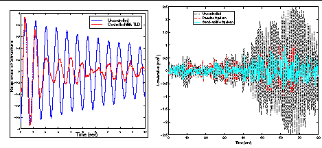
Table 1 shows
some typical results for a wind excited building. The passive system has
been designed for design speed of 30 m/s and therefore, at lower speeds,
the semi-active system does better than the passive system (which is at
non-optimal danping).
Frequency ratio: is defined as the ratio of the frequency of the damper to the frequency of the structure. Typically, auxiliary devices are tuned to the first modal frequency of the structure. A good rule of thumb is for mass ratios of 1% to have a tuning ratio of 0.99.
Length ratio: is defined as the ratio
of length of the horizontal part of the liquid in the U-tube to the total
length of water in the U-tube. The total length of liquid column is determined
by the frequency of the damper. To get an idea of the size of these tubes,
a building of 0.16 Hz natural frequency (6.3 sec time period) requires
20 meters of liquid. Typical length ratios are between 0.6-0.7. This means
the designer needs about 10 meters of vertical tube (5 m on each side and
5 meters for liquid oscillations to develop) and 12 meters of horizontal
tube.
Area ratio: is the ratio of the cross-sectional
area of the horizontal part of the U-tube to the cross-sectional area of
the vertical part of the tube. In most cases it can be kept as unity. However,
additional architectural benefits can be derived from the configuration
with variable area ratio. The total cross sectional area can be calculated
once the length of the liquid column and the mass ratio have been determined.
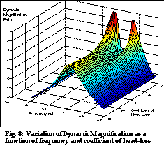
Coefficient of Head-loss: The damping
introduced by the orifice/valve in the TLCD, by it very nature, is quadratic
in nature. however, equivalent linearization can yield approximate linear
damping at various amplitudes of excitation. The design process needs to
calculate the variation of this head-loss coefficient for the particular
valve used as a function of the valve angle opening. Figure 8 shows the
variation of the dynamic magnification factor as a function of the coefficient
of head-loss and the frequency ratio.
Multiple dampers: Multiple units of
liquid dampers can be used to distribute the dampers spatially. In this
regard one can have either multiple-tuned or multiple-slightly-detuned
configurations. The proposed multiple-slightly- detuned damper configurations
are known to have more robust dynamic characteristics, i.e., improved effectiveness
under variations in frequency and damping of the primary system.
Thus the major focus of this research is
the design and development of smart liquid dampers to maintain optimal
damping levels under different loading conditions. On a more practical
note, these next generation of liquid dampers would herald the new paradigm
of vibration control in the design/construction industry. The NatHaz laboratory
has been working on all aspects of these dampers, namely, the modeling,
design, construction, algorithms, testing and cost and reliability analysis.
The researchers would like to acknowledge the support given by the National
Science Foundation under the NSF Structural Control Initiative.
Other Selected References
1.Kareem, A., (1993), "Liquid Tuned Mass Dampers: Past, Present and Future," Proceedings of the Seventh U.S. National Conference on Wind Engineering, Vol. I, Los Angeles.
2.Kareem, A. and Kline, S., (1995), "Performance of Multiple Mass Dampers under Random loading," Journal of Structural Engineering, ASCE, Vol.121, No.2, 348-361.
3.Kareem, A. and Sun, W.J., (1987), "Stochastic Response of Structures with Fluid-containing Appendages," J. of Sound and Vibration, 119(3), 389-408.
4.McNamara, R. J., (1977), "Tuned Mass Dampers for Buildings," Journal of Structural Division, ASCE, 103, 9, pp. 1785-1789.
5.Sakai, F. and Takaeda, S. (1989), "Tuned Liquid Column Damper - New Type Device for Suppression of Building Vibrations," Proceedings International Conference on High Rise Buildings, Nanjing, China, March 25-27.
6.Yalla, S.K., Kareem, A., and Kantor, J.C. (2000), "Semi-Active Tuned Liquid Column dampers," submitted to Engineering Structures.
7.Yalla, S.K., Kareem, A., and Abdelrazaq, A. K. (2000), "Risk-based Decision Analysis for the Building Serviceability", Proceedings of the 8th ASCE Speciality Conference on Probabilistic Mechanics and Structural Reliability, University of Notre Dame, July 24-26.
8.Yalla, S.K., Kareem, A. and Kantor, J.C. (1998), "Semi-Active Control Strategies for Tuned Liquid Column Dampers to Reduce Wind and Seismic Response of Structures," 2nd World Conference on Structural Control, Kyoto, June 28-July 2nd.