Click image to open a larger image
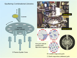
Combinatorial Sputtering:
The sputtering system includes five fixed 2" sputtering sources, with computer controlled shutters. The sputtering guns operate under either DC or RF power and can deposit material from either metallic or insulating targets. The system is designed to process 2" diameter wafers. Rotation of the mask carousel and substrate holder under computer control allows the substrate to be positioned above any of the guns with any mask positioned between. A program sequentially selects gun/mask combinations to deposit a series of multilayer samples with varying compositions on the substrate.
Discrete composition libraries are formed by depositing through a set of twelve laser etched stainless steel quaternary shadow masks. There are four basic mask designs, with each mask being used in three different orientations (rotated 90° from each other).
An example of a mask set for use with a multichannel microelectrode array (MMA) testing system is shown. Here each library member sits on an electrode that is biased individually. The measurements on the member pads are performed in parallel. A set of TiN "capture pads" and conductive traces is first deposited through a pattern defined in either a contact mask or an exposed resist layer.
The combinatorial library design masks have 64 variable composition pads along with 12 fixed composition reference pads (indicated in red on the periphery. The use of reference pads permits easy comparison between libraries. The blue pads in the three mask designs indicate the openings in the quartile masks through which deposition would occur in a sequential fashion. A total of 12 such masks (again employing 90° rotations) are employed to build a library.
Click image to open a larger image
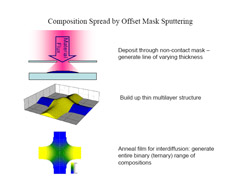
Offset Mask Sputtering:
Through the use of a simple masking approach, one can also generate continuous composition gradients in this system. If the mask does not contact the substrate, the size of the deposited feature will be larger than the opening in the mask. The extent of flux spreading will depend on the mask substrate separation. A series of "slot" masks are used, which consist of intersecting slots through which material is deposited. These masks are held a fixed distance (~1 mm) from the substrate through the use of spacer rings. By using two or three crossing slots one can generate binary or ternary phase fields, as shown schematically. Multiple layers are deposited using the masks sequentially, followed by a diffusion step. The result after diffusion is a composition gradient of varying thickness.
Click image to open a larger image
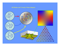
Ternary Library Formation:
This shows an example mask set (3 masks) for depositing both binary and ternary composition spreads. A different material is deposited through each of the masks. The square pads around the periphery provide spots for x-ray analysis. The composition gradient after annealing is shown in the upper right.
Click image to open a larger image
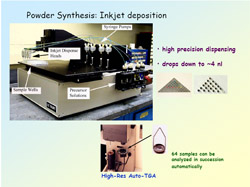
Inkjet Dispensing:
A drop-on-demand printer is used for synthesizing powders combinatorially. It combines syringe pumps with inkjet dispensers, and incorporates a computer controlled x-y-z table. Powder precursors (usually nitrates in solution with a chelating agent and a polyhydroxyl alcohol, i.e. the Pechini technique) are dispensed into small TGA crucibles. During deposition and processing, the crucibles rest in wells on a Hastelloy plate. The samples can then be characterized sequentially in an autoloading TGA. This technique is being used in catalyst development.
Click image to open a larger image
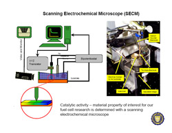
Scanning Electrochemical Microscopy:
Gradient libraries are characterized for their electrochemical activity with a scanning electrochemical microscope.
During scanning near the surface, the electrochemical current between a tip and a sample (the combinatorial library substrate) is measured. For fuel cell work, the SECM uses the proton/hydrogen redox couple as the tip reaction. Protons are reduced at the tip, and the tip potential is varied to yield conditions where protons are reduced at a diffusion-controlled rate. When the tip is near (~10 microns) a surface which can oxidize hydrogen back to protons a positive feedback situation occurs, such that the current will increase as the tip approaches the surface.
Click image to open a larger image
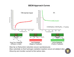
SECM Cont'd.:
Negative feedback is typically observed as the tip nears an insulating or non-reactive surface. As the diffusion of protons from the solution to the tip is made more difficult due to the reduced space, a decrease in the electrical current with tip/substrate distance is observed. Positive feedback can be observed when approaching a reactive material where the surface acts to promote hydrogen oxidation. In this case the tip current will increase because the material is such that it can oxidize the hydrogen that is produced at the tip back to protons (H2 –> 2H+ + 2e- ). Under these conditions the current steadily increases as the tip gets closer to the substrate, or as the rate of reaction at the substrate increases. Hence, one can use an approach curve (the change in tip current with distance to the substrate) to characterize the electrochemical behavior of the surface.
Click image to open a larger image
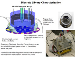
Multielectrode Microarray:
For parallel characterization of thin film fuel cell catalyst libraries we use a multielectrode microarray. This figure shows a schematic cutaway diagram of an assembled microarray cell for characterization of discrete libraries. Gold pogo probes around the wafer periphery make contact between a multichannel potentiostat and TiN leads that connect to the catalyst library pads. Suspended in the electrolyte are a reference electrode in the center, an air stone for bubbling gas to the right, and a Pt-coated Ti mesh electrode that runs completely around the edge (cutaway in the above diagram). A Teflon coated lid holds these items in place and seals the cell from the atmosphere. The figure on the right shows an actual wafer with the TiN electrode pattern, while the figure at the bottom shows the assembled cell.