Lab 3: Terrain Viewer
Due: Thursday, September 9th, 2010 (before lab session ends)
Create a program, tview, that loads a terrain file from disk, allows the user to navigate through the scene, and renders the terrain using a couple of OpenGL primitives. For this lab assignment, you will be given a set of code to use as a base. There are comments scattered throughout the code indicating which portions you will modify for this assignment; you should be able to find them by following the instructions for each section below. The code itself can be found at lab_03.tar.gz. You are expected to place your name in the main.cpp source file and comment any code you add or modify. The point.h and point.cpp files contain definitions of a simple Point class, which can be used for storing the terrain data.
Input
Input to the program is given as a 2D image of height values (i.e., a heightmap). The input file will start with a single line containing two integers, denoting the length and width of the heightmap. There will follow length lines of text in the file, each of which contains width floating point values which represent the height of the terrain at that point. Assume the spacing between points is one meter in each dimension. In other words, the jth value in the ith line of the heightmap will yield the point (i, height, j), where height is the value stored in the heightmap. A simple input file might look like:
5 5
0.0 0.1 0.2 0.1 0.0
0.1 0.3 0.5 0.3 0.1
0.3 0.5 1.0 0.5 0.3
0.1 0.3 0.5 0.3 0.1
0.0 0.1 0.2 0.1 0.0
The data file we will be used can be found online at all_campus.dem. You must write the code to load input files. It is recommended that you store the data in a global vector of Points; one already exists for your convenience (terrainPoints).
Camera Control
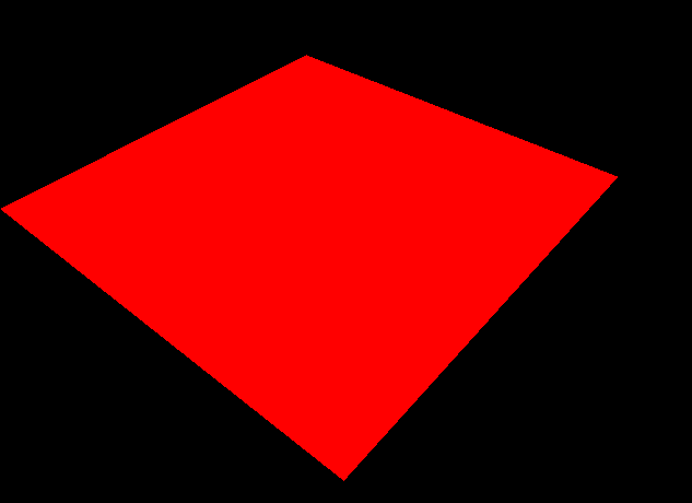
When you compile and run the base code, you should see a red plane:
Your first step is to implement camera control scheme based on the spherical coordinates scheme described in class. The user should be able to rotate the camera's direction by holding down the left mouse button and dragging: moving the mouse left and right should make the camera look left and right, and moving the mouse up and down should move the camera direction accordingly. Specifically, the user’s mouse motion should correspond to changes in cameraTheta and cameraPhi, which should be mapped to spherical coordinates using the following equations inside the recomputeOrientation() function:
camera X direction <=  sin( cameraTheta ) * sin( cameraPhi )
camera Y direction <= -cos( cameraPhi )
camera Z direction <= -cos( cameraTheta ) * sin( cameraPhi )
Pressing 'w' should move the camera forward (along the looking direction), and 's' should move the camera backwards (along the negative looking direction).
Terrain Rendering
Once camera control is complete, you will focus on visualizing the terrain data with some simple OpenGL primitives. For efficiency reasons, the terrain will be rendered using a display list. The code to create a display list, which will get rendered every frame, already exists inside the generateTerrainDL() function. Remove the code that renders a red plane and replace it with the code to render the terrain as described below.
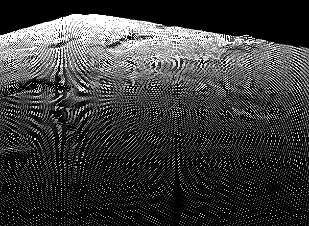
Part 1 - Points
First, render the terrain as a series of points using GL_POINTS. Don’t worry about color for now. Once this is finished, your output should look like the following:
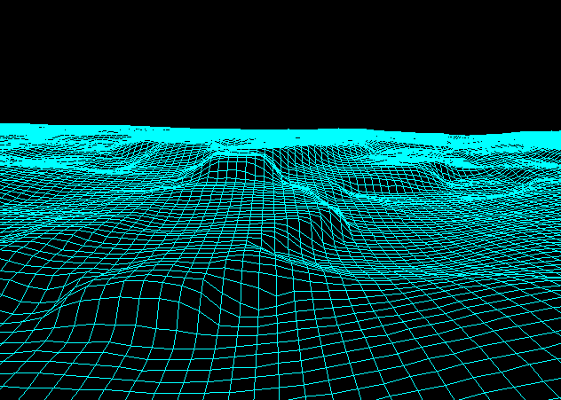
Part 2 - Lines
Next, render the terrain with a grid of lines. The lines should be in a different color than the points. You can think of this as a wireframe visualization of the solid terrain; it should help visualize the structure of the terrain, but the lines themselves are quick to generate and render. The simplest way to generate this rendering is to use GL_LINE_STRIP and iterate over the terrain twice: in the first iteration, draw a line strip for each column (i.e., create vertical stripes across the terrain), and then in the second iteration, draw a line strip for each row (i.e., create horizontal stripes across the terrain). If you disable point rendering, the terrain should look something like this:
An option to enable or disable point rendering is optional; rendering both points and lines at the same time is acceptable for this assignment, but the two should be rendered in different colors.
Usage
To specify the input data file, your program should have at least the following command line interface:
usage: tview [options] <datafile>
Options:
    -h         Show this help message
An example invocation would be:
$ ./tview all_campus.dem
Feel free to add additional flags and options to modify your programs behavior at runtime.
Submission
Demonstrate the tview executable to the instructor or TA before the lab session is over. Once verified, place the source code and Makefile in your course dropbox:
/afs/nd.edu/coursefa.10/cse/cse40166.01/dropbox/<afsid>/lab3
Do not include the DEM files you used.