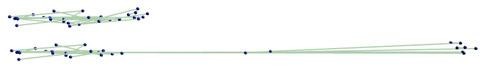
 Simulation of deformation of a small size network. (Upper): initial network; (lower): deformed network.
Two-state kinetic model for studying fibrin(or fibrinogen) - platelet integrin binding
We implemented preliminary version of the two-state model for the αIIbβ3 integrin - fibrin adhesion. The model describes unbinding kinetics of αIIbβ3 integrin - fibrin (or fibrinogen) complex from two possible states (low binding affinity and high binding affinity) as observed in experiments. Transition between two states is assumed to be at equilibrium. Given a pulling force acting on the αIIbβ3 integrin - fibrin (or fibrinogen) complex, the model calculates the probability that this bond breaks. More information about the model of the platelet-substrate binding can be found in our paper [link]:
Ziheng Wu, Zhiliang Xu, Oleg Kim, Mark Alber, "Three-dimensional multi-scale model of deformable platelets adhesion to vessel wall in blood flow" Phil. Trans. R. Soc. A, 372(2021) 2014.
The [link] to the β version of the Matlab code implementation of the fibrin(or fibrinogen) - platelet integrin binding kinetics model. The code is also available from gitHub by searching usename "notredame-compbio".
In our 2017 scientific report [ paper ], we introduced the two-state kinetic model for studying fibrin(or fibrinogen) - platelet integrin binding. We found that αIIbβ3 binding to polymeric fibrin can be segregated into two binding regimes, one with weaker rupture forces of 30–60 pN and a second with stronger rupture forces >60 pN that peaked at 70–80 pN. However, we found that the mechanical stability of the bimolecular αIIbβ3-ligand complexes had the following order: fibrin polymer > fibrin monomer > fibrinogen. These quantitative differences reflect the distinct specificity and underlying molecular mechanisms of αIIbβ3-mediated reactions.
Current status of the model and code development: completed.
Micro-structure-based model of fibrin network mechanics
Program Description
The program simulates stretching behaviour of fibrin network, where fibers are represented as linear or non-linear springs connected with branch points. It uses second order Runge-Kutta method to solve system of differential equations that describes dynamics of the network.Parameters of the Model.
The code can be run from the terminal, a command sent to begin the simulation may look like this:
Simulation of deformation of a small size network. (Upper): initial network; (lower): deformed network.
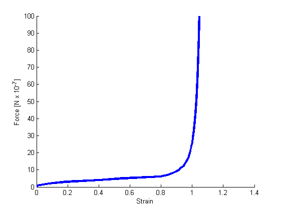 Strain-force relation of the simulated network.
More information related to the fibrin network model can be found in our paper [link]:
E. Kim, O.V. Kim, K.R. Machlus, X. Liu, T. Kupaev, J. Lioi, A.S. Wolberg, D.Z. Chen, E.D. Rosen, Z.-L. Xu and M. Alber, "Correlation between fibrin network structure and mechanical properties: an experimental and computational analysis" Soft Matter, 7:4983-4992, 2011.
The [link] to the β versions of the code implementing the fibrin network model.
The [link] to the β versions of the code for generating random network.
Code of the model for simulating diffusion of hemostatic factors under static conditions
The model of a thrombus employs a composite spherical structure with an impermeable core (activated platelets and fibrin) and a permeable shell (fibrin cap). Hemodynamics is modeled using Newtonian incompressible steady axisymmetric flow with a constant inlet velocity. In the thrombus model, a creeping flow around the thrombus is described by the Stokes and continuity equations in spherical coordinates. Flow inside the permeable fibrin cap is described by the Brinkman and continuity equations which accounts for an effective fluid viscosity of porous medium and a uniform fibrin cap permeability. The surface of the thrombus core is assumed to be nonpermeable and no-slip boundary conditions are imposed at the core boundary. Continuity of the velocity vector and the stress tensor are stated on the surface of the fibrin cap and a uniform flow is imposed at infinity. Protein transport through and near the thrombus is modeled by the diffusion-advection equation coupled with fluid dynamics equations.
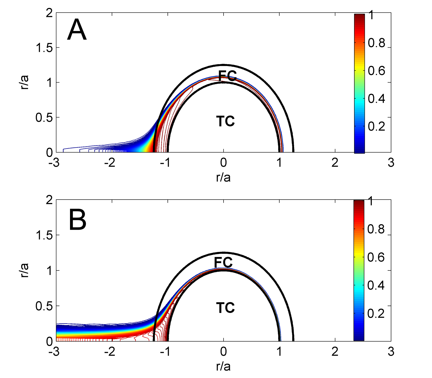 "Simulation results of thrombin distribution for low (A) and highly (B) permeable fibrin networks after 75 ms of being exposed to external flow, . ‘TC’ and ‘FC’ denote a thrombus core and a fibrin cap.
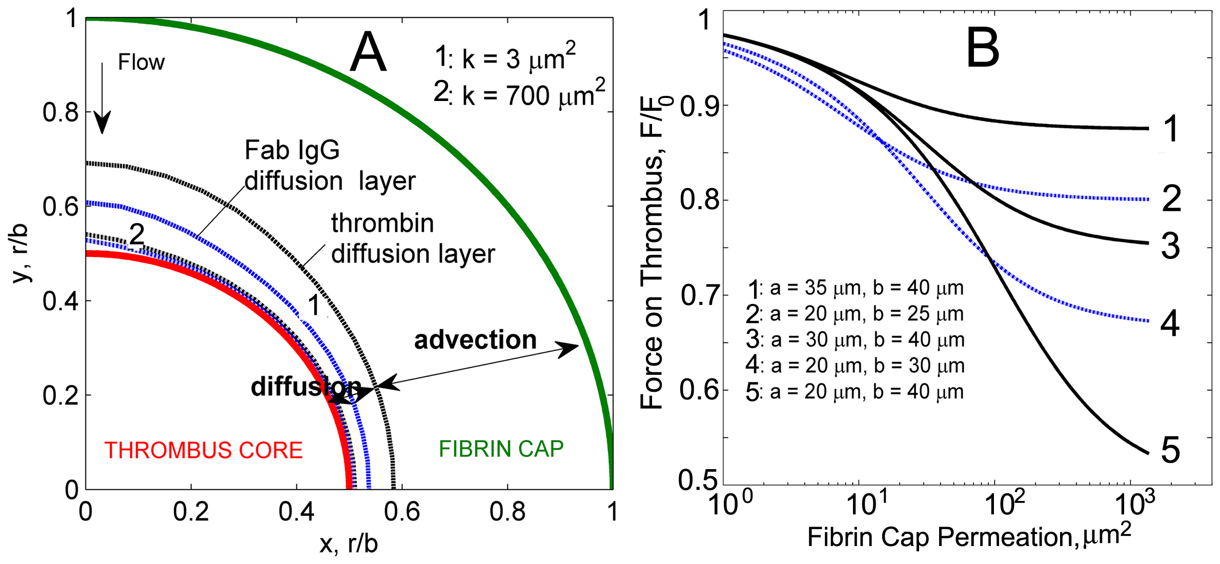 Diffusion and advection layers identified in the fibrin cap for thrombin and Fab IgG. Diffusion prevails near the thrombus surface and depends on molecular size. Smaller than Fab IgG complexes thrombin molecules have higher mobility resulting in thicker diffusion layer. Diffusion layer profiles for thrombin and Fab IgG for low and high fibrin cap permeabilities are shown. B: Force acting on a thrombus surface as a function of the permeability of the fibrin cap for different radii values of the core and the thrombus. For each permeability value, the force is non-dimensionalized by the force acting on a nonpermeable thrombus of the same size.
More information about the model for simulating diffusion of hemostatic factors through blood clot can be found in our paper [link]:
Kim OV, Xu Z, Rosen ED, Alber MS. "Fibrin networks regulate protein transport during thrombus development". PLoS Comput Biol. 2013 Jun 13;9(6):e1003095.
The [link1 and link2 ] to β versions of the Matlab program implementing the diffusion model.
Code for Fibrin Network Segmentation and Structure Analysis in 3D Confocal Microscopy Images can be found at [link]
Model Predictions of Deformation, Embolization, and Permeability of Partially Obstructive Blood Clots under Variable Shear Flow
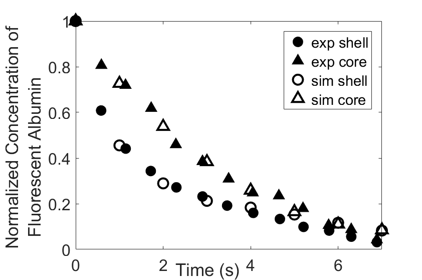
Thromboembolism, one of the leading causes of morbidity and mortality worldwide, is characterized by formation of obstructive intravascular clots (thrombi) and their mechanical breakage (embolization). A novel two-dimensional multi-phase computational model [paper ] is introduced that describes active interactions between main components of the clot, including platelets and fibrin, to study the impact of various physiologically relevant blood shear flow conditions on deformation and embolization of a partially obstructive clot with variable permeability.Model calibration. The model was first verified by calculating the total shear force acting on the clot surface. Figure below shows the total shear force for seven values of permeability of the shell region. The simulation code is [calibration code ]. The movie [diffusion ] shows the transport of albumin through the clot.
Relationship between clot permeability and its mechanical stability. To evaluate whether variations in clot permeability affect clot stability, we have simulated clot deformation dynamics and embolization as the permeability of the shell region varied from 10(-13) m2 to 10(-11) m2 while the core of the clot was assumed to have a low and constant permeability (10(-14) m2). The shear rate is fixed to be 1000s(-1). The related simulation code is [ permeability simulation code ]. Movies below shows deformation of the clot at various permeabilities: 10(-11) m2, 10(-12) m2 and 10(-13) m2.

Three-phase Model of Visco-elastic Incompressible Fluid Flow and its Computational Implementation
We generalized the above blood clot model for modeling complex fluids. A novel thermodynamically consistent three-phase model of a mixture of Newtonian and visco-elastic fluids [paper ] is developed by Energetic Variational Approach. The model which automatically satisfies the energy dissipation law and is Galilean invariant, consists of coupled Navier-Stokes and Cahn-Hilliard equations. Modified General Navier Boundary Condition with fluid elasticity taken into account is also introduced for using the model to study moving contact line problems. Energy stable numerical scheme is developed to solve system of model equations efficiently.The simulation code of the paper is [ code ], which implements the energy stable scheme introduced in the paper.
All source codes and programs are distributed for academic use only.

For any question about the algorithm and the code, feel free to send an email to Mark Alber (malber@ucr.edu) or Zhiliang Xu (zxu2@nd.edu)