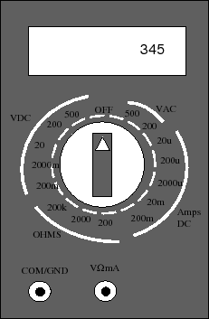
In the middle of DMM's faceplate you will find a large rotary rotary switch, an LCD (liquid crystal) display, and two (sometimes 3) jacks for probes. The rotary switch is used to switch the DMM into its mode. It has one of 4 operating modes. It can either be used to measure constant voltages (VDC), sinusoidal voltages (VAC), constant currents, or resistances (ohms). Note that for each of these operating modes, there are 3-4 additional submodes that determine the largest value that can be displayed on the DMM's LCD. For example, if you were to set the switch to VDC 200m, then the largest voltage to be displayed on the LCD will be 200 milli-volts.
The actual measurements are made with two probes. One
probe is black and the other is red. The black probe
is usually connected to the COM/GND jack on the front of
the DMM. The red probe is usually connected to the
other jack (![]() ). The black probe is usually
taken to be the reference or ground node.
). The black probe is usually
taken to be the reference or ground node.
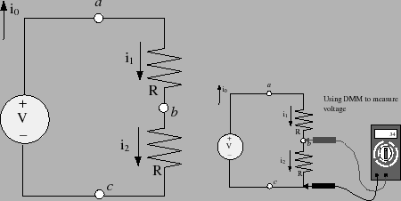
You can use the DMM to measure DC currents, DC voltages and resistance. To measure a DC voltage between two points on a circuit, you need to connect the black probe to the bottom end of the branch and the red node to the top end of the branch. Once the DMM switch is placed to one of the VDC positions, the voltage over that branch will be displayed on the DMM's display. Figure 13 shows how to make the connections. The lefthand picture shows the circuit schematic and the righthand picture shows where to connect the DMM to measure the voltage across the second resistor.
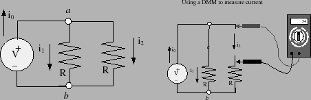
To use a DMM to measure current, we need to make some
changes to the original circuit. Recall that current is
the rate at which electrons flow past a point in a
circuit. To measure this flow, we need to insert the DMM
into the flow. To do this we need to break the circuit.
Figure 14 shows how to do this.
The lefthand drawing in the figure is the circuit and we
want to measure the current flowing through the second
resistor ![]() . The righthand drawing shows that we
actually have to disconnect one terminal of the resistor.
The red lead of the DMM will be connected to one of the
free ends and the black lead will be connected to the
other free end. These connections are shown in the
righthand picture of figure 14. Once
the DMM rotary switch is set to the current measuring
position, the display on the DMM will show the actual
current flowing through the second resistor.
. The righthand drawing shows that we
actually have to disconnect one terminal of the resistor.
The red lead of the DMM will be connected to one of the
free ends and the black lead will be connected to the
other free end. These connections are shown in the
righthand picture of figure 14. Once
the DMM rotary switch is set to the current measuring
position, the display on the DMM will show the actual
current flowing through the second resistor.
You may also use the DMM to measure a resistor's resistance. To do this, first remove the resistor from the circuit and set the DMM's rotary switch to one of the resistor positions. Connect one probe to one end of the resistor and the other probe to the other end of the resistor. The measured resistance should appear in the DMM's display. Note that it is important that the resistor actually be removed from the circuit. If you attempt to measure the resistance of a resistor while it is still in the circuit, then you will not get the correct answer. You will be measuring the so-called equivalent parallel resistance of your resistor with the rest of the circuit.