The ![]() Stamp11 module is built on a printed circuit board
(PCB). A PCB is a non-conducting board upon which there
are conducting strips. The components of your circuit are
then connected to these conducting strips. The connections
can be made using solder or wire-wrap. The problem is that
these two types of connections are rather permanent. If
you make a mistake in your initial circuit, it is difficult
to "undo" what you've done. As a result, these methods are
inconvenient for prototyping circuits.
Stamp11 module is built on a printed circuit board
(PCB). A PCB is a non-conducting board upon which there
are conducting strips. The components of your circuit are
then connected to these conducting strips. The connections
can be made using solder or wire-wrap. The problem is that
these two types of connections are rather permanent. If
you make a mistake in your initial circuit, it is difficult
to "undo" what you've done. As a result, these methods are
inconvenient for prototyping circuits.
To build prototype circuits, we'll use a special device known as a solderless breadboard. We often refer to such breadboards as proto-boards.
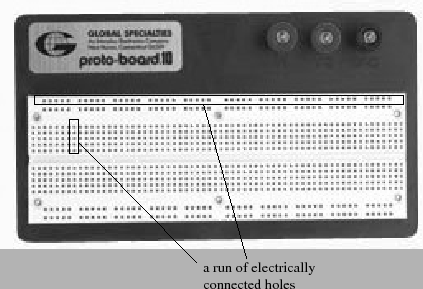
Figure 11 is a top down view of a standard proto-board. The protoboard consists of a set of holes that are just the right size for accepting the leads of electrical devices. (such as a resistor lead). The holes in the proto-board are electrically connected in a systematic manner so you can easily build electrical circuits by simply inserting the leads of your circuit components into the protoboard's holes.
The proto-board's holes are electrically connected in a systematic manner. A long row of holes on the top (bottom) of the board are electrically connected. These rows are usually connected to the power supply and ground and we refer to them as power buses. In the middle of the board, you'll find two columns of holes stacked on top of each other. These columns are also electrically connected. We usually insert components into these holes. In figure 11, we've circled the electrically connected groups of holes on the proto-board.
The nice thing about a proto-board is that you can easily build circuits by inserting one end of a device's lead into one hole and then inserting another component's lead into one of the electrically connected holes. This means that it is easy and fast to build circuits.
It is important, however, that one is NEAT in building prototype circuits. Being neat means that wires of appropriate lengths are used and that wires and components lie flat against the proto-board (if possible). It is highly recommended that your wires and components run in vertical and horizontal directions. Neat breadboards are important for more than aesthetic reasons. Careful wiring makes it easier to debug your circuits when they don't work. It also prevents accidental shorting of components and excessive parasitic effects that can greatly degrade the performance of your circuit.