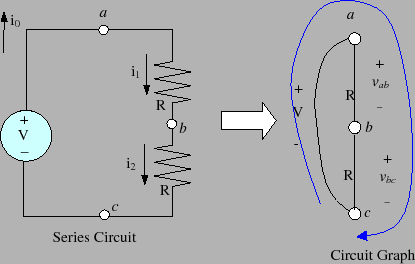
As was mentioned earlier, a circuit is an interconnection of electrical devices. For the most part, we'll be concerned with interconnections of two-terminal devices such as resistors and diodes. An example of such a circuit is shown below in figure 9. The lefthand picture is the circuit diagram and the righthand picture is the circuit's graph.
Circuit analysis requires that we determine the voltage
across and current through all branches of a circuit. For
the circuit in figure 9, the independent
voltage source makes it easy to specify the voltage across
nodes ![]() and
and ![]() , but how do we analyze the rest of the
circuit? To do this, we need to invoke two special physical
laws that lie at the heart of all circuit analysis. In
particular, we need to use the laws known as Kirchoff's current law or KCL and Kirchoff's voltage law
KVL. These two laws are conservation principles that
must always be obeyed by any passive circuit. We can use
these laws to help determine the voltages and currents in
the circuit's branches.
, but how do we analyze the rest of the
circuit? To do this, we need to invoke two special physical
laws that lie at the heart of all circuit analysis. In
particular, we need to use the laws known as Kirchoff's current law or KCL and Kirchoff's voltage law
KVL. These two laws are conservation principles that
must always be obeyed by any passive circuit. We can use
these laws to help determine the voltages and currents in
the circuit's branches.
Kirchoff's Voltage Law (KVL) is stated with respect to a loop in a circuit's graph. It states that: `` the algebraic sum of the voltages around any loop equals zero. `` A loop is a sequence of connected branches that begin and end at the same node. Figure 9 marks one of the loops in our circuit. This is the loop formed from branches
The other important circuit relation is Kirchoff's current
law. Kirchoff's Current Law (KCL) is stated as
follows:
``
The algebraic sum of current at any node is zero.
``
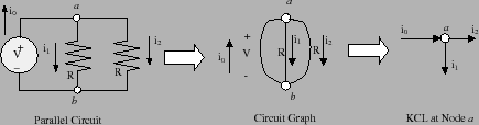
To explain what this statement means, let's consider the
circuit shown in figure 10. This figure
shows an independent source of ![]() volts connected to a
resistive network . The single node
volts connected to a
resistive network . The single node ![]() of this circuit is
shown in the righthand drawing of figure
10. At this node, we see three currents.
Two of these currents
of this circuit is
shown in the righthand drawing of figure
10. At this node, we see three currents.
Two of these currents ![]() and
and ![]() are leaving node
are leaving node ![]() and the third current
and the third current ![]() is entering node
is entering node ![]() . Currents
that are entering a node are assumed to have a positive
sign, whereas currents leaving a node have a negative sign.
By Kirchoff's current law, the algebraic sum (which takes
into account the sign of the currents) must be zero. This
means, therefore, that
. Currents
that are entering a node are assumed to have a positive
sign, whereas currents leaving a node have a negative sign.
By Kirchoff's current law, the algebraic sum (which takes
into account the sign of the currents) must be zero. This
means, therefore, that
Kirchoff's current law is simply a statement that charge cannot accumulate at the nodes of a circuit. This actually makes quite a bit of sense if you realize that the nodes are perfect conductors and therefore provide no place for charges to rest. This principle is identical to concepts found in fluid dynamics. Namely that if you look at the fluid flowing into one end of a pipe, you expect the same amount of fluid to flow out the other end. If this did not occur, then fluid would accumulate in the pipe and eventually cause the pipe to burst. KCL is nothing more than an electrical equivalent of this intuitive physical idea from fluid mechanics.
The key issue is to see how we can use KVL, KCL and Ohm's law to determine all of the branch voltages and currents in a specified circuit. We use the circuit in figure 9 to illustrate this process. What we will now do is determine all of the currents and voltages in this circuit.
We begin by using KCL at node
![]() ,
, ![]() , and
, and ![]() . Remember that KCL states that the sum
of the currents entering a node must equal the sum of the
currents exiting a node. Applying KCL to nodes
. Remember that KCL states that the sum
of the currents entering a node must equal the sum of the
currents exiting a node. Applying KCL to nodes ![]() ,
, ![]() ,
and
,
and ![]() will therefore result in three different equations
will therefore result in three different equations

We now look at the voltages over each of the branches in
this circuit. Because arc ![]() is an independent
voltage source, we know that
is an independent
voltage source, we know that ![]() volts. The other
arcs, however, are resistors and this means that they must
satisfy Ohm's law. Applying Ohm's law to these branches
allows us to conclude that
volts. The other
arcs, however, are resistors and this means that they must
satisfy Ohm's law. Applying Ohm's law to these branches
allows us to conclude that

Finally, we use KVL (as before) to write down a single loop equation relating all of the voltages,
On the way, however, we determined that all of the other
currents and voltages in the circuit can be written as
functions of this current ![]() . Recall, that we deduced
that
. Recall, that we deduced
that
![]() , so that we now know all of the
currents in the circuit. Once the currents are known, we
can use Ohm's Law to readily deduce that
, so that we now know all of the
currents in the circuit. Once the currents are known, we
can use Ohm's Law to readily deduce that
![]() . In other words, this circuit evenly
divides the voltage supplied by the independent voltage
source between the two resistors in the circuit.
. In other words, this circuit evenly
divides the voltage supplied by the independent voltage
source between the two resistors in the circuit.