An ideal resistor is a two-terminal device in which
the voltage across the terminals is proportional to the
current flowing through the device. The constant of
proportionality is denoted as ![]() , the resistance of
the device. This resistance is measured in units of volts per ampere or ohms (denoted by the Greek
symbol
, the resistance of
the device. This resistance is measured in units of volts per ampere or ohms (denoted by the Greek
symbol ![]() ). In mathematical terms, this relationship
is written as
). In mathematical terms, this relationship
is written as
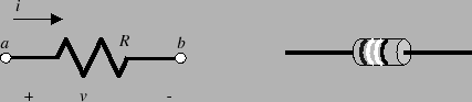
The symbol for a resistor is shown by the lefthand picture
in figure 2. The righthand picture in
figure 2 depicts the actual component.
From this picture you will find that the resistor is a
small cylindrical component with two wire leads coming out
of each end. Often the device will have colored bands
around it. These bands are a color code specifying the
value of the resistor in ![]() .
.
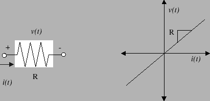
Equation 1 is the equation for a linear resistor. The linearity of the device can be
readily appreciated if we draw the current-voltage
characteristic or I-V curve for the device. This curve
plots the voltage ![]() across the device as a function of
the current
across the device as a function of
the current ![]() through the device. Figure
3 shows the I-V characteristic for a
linear resistor. This characteristic is a straight line.
The resistance is given by the slope of the line.
through the device. Figure
3 shows the I-V characteristic for a
linear resistor. This characteristic is a straight line.
The resistance is given by the slope of the line.
Two special types of resistors are the short circuit and open circuit. We define a short circuit as a two-terminal device device whose resistance is zero. An open circuit is a two-terminal device whose resistance is infinite.
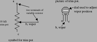
A special type of a resistor is a potentiometer. We
sometimes refer to them as pots. The potentiometer has
three terminals. There are two terminals at either end of a
resistor (![]() and
and ![]() ) and a third terminal connection
(called the wiper) that taps into the middle of the
resistor. The lefthand picture in figure 4
shows the symbol for a potentiometer, which is a resistor
with the wiper lead tapping into the middle of the device.
The righthand picture shows the physical device. This
particular trim pot has a dial on the front that allows you
to mechanically adjust the position of the wiper. The
first and third leads on the bottom of the device
correspond to the two ends of the resistor and the wiper
lead is the lead in the middle.
) and a third terminal connection
(called the wiper) that taps into the middle of the
resistor. The lefthand picture in figure 4
shows the symbol for a potentiometer, which is a resistor
with the wiper lead tapping into the middle of the device.
The righthand picture shows the physical device. This
particular trim pot has a dial on the front that allows you
to mechanically adjust the position of the wiper. The
first and third leads on the bottom of the device
correspond to the two ends of the resistor and the wiper
lead is the lead in the middle.
You can use the potentiometer to construct a resistor whose
resistance changes when you change the wiper position (by
turning the dial on the front of the pot). This is simply
done by connecting lead ![]() to the circuit and connecting
the wiper (lead
to the circuit and connecting
the wiper (lead ![]() ) to the circuit. The lefthand picture
in figure 4 shows which two leads you must
connect in order to get a variable resistor. By changing
the dial position you can change the resistance between
leads
) to the circuit. The lefthand picture
in figure 4 shows which two leads you must
connect in order to get a variable resistor. By changing
the dial position you can change the resistance between
leads ![]() and
and ![]() .
.