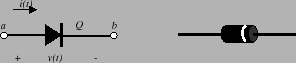
A diode is a two-terminal semiconductor device. It can be thought of as an electronic valve that only allows current to flow in one direction. The symbol for the diode is shown in the lefthand picture of figure 5. The symbol is shaped like an arrow that indicates the direction in which current may flow. The terminal marked with a positive sign is called the anode and the terminal marked with a negative sign is called the cathode. The righthand picture depicts the physical device. It looks similar to a resistor except that it has a single band on one end. In a forward biased diode, the current will flow from the end without a band to the end of the cylinder with the band.
When the voltage ![]() is positive and greater than a
minimum threshold voltage
is positive and greater than a
minimum threshold voltage ![]() , then the diode is said
to be forward biased. A forward biased diode will
conduct current
, then the diode is said
to be forward biased. A forward biased diode will
conduct current ![]() , in the direction shown in the
figure. If a diode is not forward biased, then we say it
is reverse biased. A reverse biased diode will
also conduct a current that has the opposite sense of
that shown in figure 5. This reverse
current, however, will be extremely small so that the
forward biased diode is seen as conducting, whereas the
reverse biased diode is seen as not conducting.
, in the direction shown in the
figure. If a diode is not forward biased, then we say it
is reverse biased. A reverse biased diode will
also conduct a current that has the opposite sense of
that shown in figure 5. This reverse
current, however, will be extremely small so that the
forward biased diode is seen as conducting, whereas the
reverse biased diode is seen as not conducting.
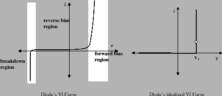
As with the resistor, the diode is completely characterized once we know the relationship between the voltage and current. The diode's IV characteristic satisfies the following equation
The lefthand plot in figure
6 has three distinct
operating regions. The forward bias region
corresponds to those positive voltages that are above a
specified threshold level. The threshold voltage,
![]() , is a function of the physical properties of the
semi-conductor material. Common values for this
threshold voltage lie between
, is a function of the physical properties of the
semi-conductor material. Common values for this
threshold voltage lie between ![]() and
and ![]() volts.
For voltages that lie below this threshold, the diode
essentially stops conducting. There is a small leakage
current that is on the order of
volts.
For voltages that lie below this threshold, the diode
essentially stops conducting. There is a small leakage
current that is on the order of ![]() . But as noted
earlier this current is extremely small. If we further
decrease the voltage, then we enter another region of
operation known as the breakdown region.
. But as noted
earlier this current is extremely small. If we further
decrease the voltage, then we enter another region of
operation known as the breakdown region.
We generally operate a diode in either its forward or
reverse biased modes. In particular, we usually
idealize this behavior so we can think of the diode as a
valve that is open when ![]() is greater than the
threshold voltage
is greater than the
threshold voltage ![]() and is closed otherwise. These
considerations lead to the simplified I-V characteristic
that is shown in the righthand graph of figure
6. In this simplified
plot, we see that the reverse bias region is idealized
so that zero current is passed in this region if
and is closed otherwise. These
considerations lead to the simplified I-V characteristic
that is shown in the righthand graph of figure
6. In this simplified
plot, we see that the reverse bias region is idealized
so that zero current is passed in this region if ![]() . If the diode is forward biased, then the current
is potentially unbounded, which means that the diode
behaves like a short circuit. In other words, a forward
biased diode behaves like a short circuit and a reverse
biased diode acts like an open circuit.
. If the diode is forward biased, then the current
is potentially unbounded, which means that the diode
behaves like a short circuit. In other words, a forward
biased diode behaves like a short circuit and a reverse
biased diode acts like an open circuit.
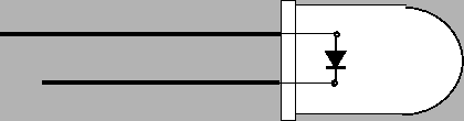
An LED is a light emitting diode. The LED emits light when it is forward biased and it emits no light when it is reverse biased. The intensity of light is proportional to the square of the current flowing through the device. Figure 7 shows a picture of an LED. Note that LEDs have two leads. One lead is longer than the other. These leads are used to indicate which end of the diode is positive (anode) and which is negative (cathode). In many cases the longer lead is the anode, but you can easily test this by connecting the LED to a battery and seeing which orientation causes the LED to light up.