An LED is a light emitting diode. A diode is a two-terminal semi-conductor device that behaves something like an electronic valve. When the diode is forward biased, then the diode can conduct a substantial current and the LED emits lights. The intensity of this light is proportional to the current flowing through the diode. A forward biased diode acts, essentially, like a short circuit. When the diode is reverse biased then only a small leakage current can flow and the diode is dark. The reverse biased diode, therefore, behaves like an open circuit. We use LED's to provide a visual indicator of the Micro-controller's state. On the docking module, for example, you will find two LEDs. One of the LEDs is lit whenever there is power applied to the module. The other LED is connected to one of the I/O ports of the MicroStamp11 and can be used to monitor the activity level of the device.
This project asks you to use the MicroStamp11 to drive a special integrated circuit that contains seven LEDs. The LEDs are arranged in a way that allows you to display numbers and letters. The typical arrangement of LEDs is shown in figure 2. By turning on the appropriate segments, we can display numbers between 0 and 9.
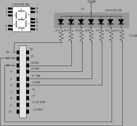
Figure 2 shows the pin assignments for
the seven segment LED (LSD3221-11). You'll need to connect
these LED's in series with a 2.2 k-ohm resistor in order to
limit the current load on the ![]() Stamp11 to a safe level.
One possible connection that uses pins 1-3 and 15-18 on the
Stamp11 to a safe level.
One possible connection that uses pins 1-3 and 15-18 on the
![]() Stamp11 is shown in figure 2. This
connection uses 4 of the 6 available I/O pins on PORTD and
3 of the 4 output pins on PORTA. This configuration keeps
pins 19 and 20 (PORTA) free so you can use the serial
interface to your personal computer.
Stamp11 is shown in figure 2. This
connection uses 4 of the 6 available I/O pins on PORTD and
3 of the 4 output pins on PORTA. This configuration keeps
pins 19 and 20 (PORTA) free so you can use the serial
interface to your personal computer.
In reviewing figure 2, you should notice that each of the LED's in the package is connected through a 2 kilo-ohm resistor to the output-pin of the MicroStamp11. This resistor is used to limit the current that flows through the diode. Remember that a forward biased LED acts as a short circuit. If we had connected the diode without the resistor, then setting one the output pins low, would have forward biased the diode. But because the diode acts as a short circuit, the current flowing through the diode and hence the MicroStamp11 would be extremely large. It would in fact be large enough to damage the Micro-controller. The resistors shown in figure 2 are in series with the diode, so that when 5 volts is dropped across the diode/resistor series combination, the current flowing through the diode will be limited by the resistor to a finite value that will not damage the MicroStamp11. It is for this reason that each of the LEDs in figure 2 has a current limiting resistor attached to it.
It is extremely important that you keep this in mind when interfacing devices to the output pins of the MicroStamp11. In all cases, you must make sure that the current drawn out of the MicroStamp11 is consistent with its internal ratings. The internal circuitry within the MicroStamp11 can only source around 10 mA at most. Anything greater than this will eventually destroy the device. Figure 3 emphasizes the importance of using current limiting resistors by showing the "right" and "wrong" way of connecting an LED to the MicroStamp11.