The preceding section showed how you might connect the
![]() Stamp11 to a seven segment LED display. We now
examine the question of reading a logical level off of an
input pin.
Stamp11 to a seven segment LED display. We now
examine the question of reading a logical level off of an
input pin.
To read the logical state of a pin, you must first make sure that the pin's direction state is set to input. After that you must provide a valid logical voltage level of zero or 5 volts to the input pin. You can then look at the appropriate bit in the port variable (PORTA, PORTD) to have the program read the logical state of the pin.
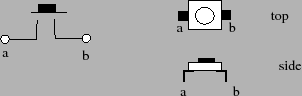
A valid logical voltage level can be applied to the pin by
using a button. The schematic symbol for a button is
shown in figure 4. The righthand drawing is
a picture of this particular button. This particular
switch has a single button. When pushed, the switch closes
the connection between terminals ![]() and
and ![]() . When
released, the connection between terminals
. When
released, the connection between terminals ![]() and
and ![]() is
an open circuit. Sometimes, we can have buttons that close
the connection on multiple pairs of terminals. Some of the
buttons in the lab may have these multiple terminal pairs.
It is recommended that you use the DMM to check which
pairs of terminals are electrically connected when the
button is pushed.
is
an open circuit. Sometimes, we can have buttons that close
the connection on multiple pairs of terminals. Some of the
buttons in the lab may have these multiple terminal pairs.
It is recommended that you use the DMM to check which
pairs of terminals are electrically connected when the
button is pushed.
Remember that for PORTD, you can set the direction state of
the pin by setting the appropriate bits in the DDRD
register. Only two of the pins on PORTA are bi-directional
and their direction states are set by the bits DDRA7
or DDRA3 in the hardware register PACTL.
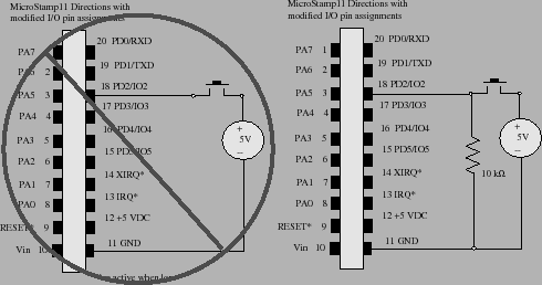
So how do we supply a valid logical voltage level to the input pin? One might suppose that the circuit shown on the left-hand side of figure 5 would work. But this circuit isn't a good design.
The reason why this particular circuit won't work well can be explained as follows. First, let's assume that the switch is closed. At this point the input pin will have a specified amount of charge sitting 5 volts away from ground. To keep that charge from draining way, the input pin is, essentially, an open circuit. So if we open the switch, there is still all of this charge sitting on the input pin. We need to give that charge somewhere to go and this is done by connecting a resistor to either the +5 volt supply or to ground. This modified and much better circuit is shown in the right-hand drawing of figure 5.
In this case, when the switch is closed, then we will have a small current going through the 10 k-ohm resistor and the potential between the input pin and GND is 5 volts. When the switch is opened, all of the charge left on the input pin will drain away to ground through this resistor and the potential at the input pin will be pulled-down to ground.
Note that the input pin circuitry is very sensitive to the voltage level applied over the device. Applied voltages in excess of 5 volts will probably destroy the MicroStamp11 in a puff of smoke.