


Next: Pre-lab Tasks:
Up: lab5
Previous: What is a clamp
In this lab you will design, build, and test a circuit that
- buffers the DAC network from the rest of the circuit
and amplifies the DAC output by a factor of two,
- compares the amplified DAC output coming out of the
buffer against a reference voltage to produce a binary
voltage between zero or 9 volts,
- and clamps the output of the comparator to 0 or 5
volts.
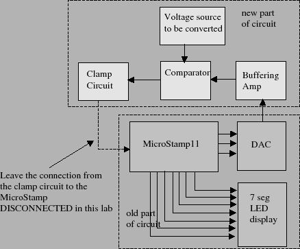
A block diagram of the complete circuit that shows the
interconnection of the ladder network, buffer, reference
voltage source, comparator, and clamp will be found in
figure 11. This figure outlines that portion
of the block diagram that was constructed in previous labs
as well as the new part you are to construct in this lab.
Please note that the connection between the clamp circuit's
output and the MicroStamp11 is left open. We don't want
you to close this connection until you are certain that the
clamp voltages lie within the proper range. You will close
this connection in the next lab.
Figure 11:
Block diagram of completed system
 |
Subsections
Next: Pre-lab Tasks:
Up: lab5
Previous: What is a clamp
Michael Lemmon
2009-02-01