A voltage amplifier is a special circuit that accepts
an input voltage, ![]() and outputs a voltage,
and outputs a voltage,
![]() that is proportional to the
input voltage. The proportionality factor
that is proportional to the
input voltage. The proportionality factor ![]() is called
the gain of the amplifier. If
is called
the gain of the amplifier. If ![]() , then the
amplifier actually does amplify the input voltage. If
, then the
amplifier actually does amplify the input voltage. If
![]() , then the amplifier attenuates the input
voltage.
, then the amplifier attenuates the input
voltage.
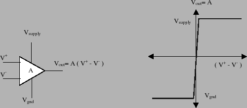
An operational amplifier or op-amp is a special
integrated circuit that accepts two input voltages, ![]() and
and ![]() . The op-amp's output is a single voltage
(relative to ground), such that
. The op-amp's output is a single voltage
(relative to ground), such that
The symbol for an operational amplifier is a triangle that has two inputs and a single output. This symbol is shown below in figure 2. The input with a positive sign is called the non-inverting terminal and the input with the negative sign is called the inverting terminal. In addition to the two inputs and single output, the op-amp must have two supply voltages. These are shown be the two extra lines coming out of the top and bottom of the triangle in figure 2. The output voltages generated by the op-amp will be confined to lie within these two supply voltages. To function properly the top supply voltage should be at least 7-9 volts and the bottom supply can be anything less than or equal to 0 volts.
As mentioned above the op-amp is an IC that acts as a
high-gain difference amplifier. The gain is, in fact, very
large, somewhere on the order of ![]() . In addition
to this the op-amp circuitry is designed so that the device
has a very high input resistance and very low output
resistance. This means that we can model the op-amp using
a dependent voltage controlled voltage source. A
dependent source is a voltage/current source whose value
is a function of some other voltage/current in the circuit.
Your textbook should discuss these idealized circuit
elements in more detail.
. In addition
to this the op-amp circuitry is designed so that the device
has a very high input resistance and very low output
resistance. This means that we can model the op-amp using
a dependent voltage controlled voltage source. A
dependent source is a voltage/current source whose value
is a function of some other voltage/current in the circuit.
Your textbook should discuss these idealized circuit
elements in more detail.
Dependent voltage sources are a very good approximation for the op-amp's behavior. In other words, the op-amp is a circuit that has been engineered to be well approximated by an idealized circuit element . This means that we can use op-amp models in a reliable manner to predict the behavior of op-amp circuits with high confidence that our analytical predictions will be duplicated by the physical device. This simple fact makes the op-amp one of the most useful building blocks in analog circuit design.
To operate properly, the op-amp must be supplied a voltage
that is larger than the range of differential input
voltages. These other voltages are called supply
voltages and they are denoted as
![]() and
and
![]() in figure 2. In practice there
are two types of op-amps. Double side op-amps have supply
voltage of
in figure 2. In practice there
are two types of op-amps. Double side op-amps have supply
voltage of ![]() volts (where
volts (where ![]() is some positive
voltage between 9 and 15 volts). This means that the output
of the op-amp can swing between these positive and negative
supply voltages. A single sided op-amp has a supply voltage
of
is some positive
voltage between 9 and 15 volts). This means that the output
of the op-amp can swing between these positive and negative
supply voltages. A single sided op-amp has a supply voltage
of ![]() volts and ground. This means that the output can
only swing from 0 to
volts and ground. This means that the output can
only swing from 0 to ![]() volts. In our labs we'll be
using a single sided op-amp known as the LM660.
volts. In our labs we'll be
using a single sided op-amp known as the LM660.
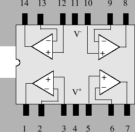
The op-amp you've been supplied with in your kit is a
standard single-sided quad op-amp (LM660). By single
sided, we mean that the supply voltages are ![]() volts
and ground (rather than
volts
and ground (rather than ![]() volts). By quad, we mean
that there are 4 op-amps on a single chip. The pin-out for
the LM660 is shown below in figure 3.
volts). By quad, we mean
that there are 4 op-amps on a single chip. The pin-out for
the LM660 is shown below in figure 3.