Let's consider a program that the MicroStamp11 is executing. A program is a list of instructions that the micro-controller executes in a sequential manner. A hardware event is something special that happens in the micro-controller's hardware. An example of such an event is the RESET that occurs when pin 9 on the MicroStamp11 is set to ground.
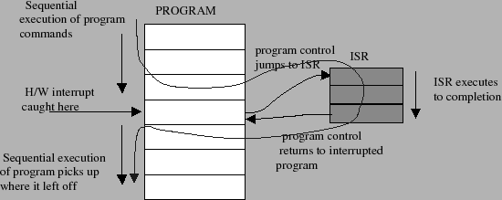
When an event occurs the micro-controller generates a hardware interrupt. The interrupt forces the micro-controller's program counter to jump to a specific address in program memory. This special memory address is called the interrupt vector. At this memory location we install a special function known as an interrupt service routine (ISR) which is also known as an interrupt handler. So upon generating a hardware interrupt, program execution jumps to the interrupt handler and executes the code in that handler. When the handler is done, then program control returns the micro-controller to the original program it was executing. So a hardware interrupt allows a micro-controller to interrupt an existing program and react to some external hardware event. This type of flow control is illustrated in figure 2.
Interrupt service routines are used to execute extremely important pieces of code in response to critical events. In an automotive system, for example, we might have a micro-controller supervising the operation of various devices on the car's dashboard. Usually, this micro-controller would be concerned with making sure the electronic gauges on the dash are displaying the correct information. If, however, the car is in a collision, then these display functions are much less important than, say, the deployment of an airbag. So, when this "collision" event occurred, we would want the micro-controller to interrupt its usual tasks in order to execute the "deploy airbag" task.
In our case, of course, our hardware events are not as
dramatic as "deploy airbag". What type of hardware events
are of interest to the ![]() Stamp11? You have already used
some of these events. We've already mentioned the RESET
interrupt that is tied to pin 9. When this pin goes low,
it generates a hardware interrupt that forces program
execution to jump to the interrupt vector
Stamp11? You have already used
some of these events. We've already mentioned the RESET
interrupt that is tied to pin 9. When this pin goes low,
it generates a hardware interrupt that forces program
execution to jump to the interrupt vector 0xFFFE.
This memory location is the default starting address
defined in vector.c. So when pin 9 goes low, the
micro-controller stops everything and begins re-executing
the program.
A table of some of the other hardware interrupts along with their interrupt vectors are found in the following table.
| interrupt vector | interrupt source |
0xFFFE |
Power on, Reset |
0xFFFA |
Watchdog timer failure (COP) |
0xFFF0 |
real time interrupt (RTIF) |
0xFFEE |
timer input capture 1, (IC1) |
0xFFEC |
timer input capture 2, (IC2) |
0xFFEA |
timer input capture 3, (IC3) |
0xFFE8 |
timer output compare 1, (OC1) |
0xFFE6 |
timer output compare 2, (OC2) |
0xFFE4 |
timer output compare 3, (OC3) |
0xFFE2 |
timer output compare 4, (OC4) |
0xFFE0 |
timer output compare 5, (OC5) |
0xFFDE |
timer overflow (TOF) |
0xFFD8 |
SPI serial transfer complete (SPIF) |
0xFFD6 |
SCI events (RDRF, TDRE) |
0xFFF8 |
illegal opcode trap |
0xFFF6 |
software interrupt (SWI) |
This table is only a partial list of the hardware events
that can be used to interrupt program execution. In using
the ![]() Stamp11 to generate a PWM signal, we'll only need
to focus on one of the hardware events; the output compare
event (
Stamp11 to generate a PWM signal, we'll only need
to focus on one of the hardware events; the output compare
event (OC4). This is the same hardware event that
is used by the kernel function pause.