An ![]() circuit contains a single resistor,
circuit contains a single resistor, ![]() and a
single capacitor
and a
single capacitor ![]() . From your course textbook you should
already know that a capacitor is a two-terminal device
whose voltage,
. From your course textbook you should
already know that a capacitor is a two-terminal device
whose voltage, ![]() , and current,
, and current, ![]() , satisfy the
following relationship,
, satisfy the
following relationship,
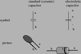
Capacitors come in a variety of forms. One of the most common types of capacitors is a ceramic capacitor. A ceramic capacitor is shaped like a disk with two leads coming out of it. A picture of the schematic symbol of the capacitor is shown in figure 1. This symbol consists of two bars (representing the capacitor's two plates) with two leads coming out of them. A picture of a representative ceramic capacitor is also shown in figure 1. Another type of capacitor is the electrolytic capacitor. The symbol for an electrolytic capacitor has one of its plates curved and the top plate is marked with a plus sign (see figure 1). Electrolytic capacitors are constructed using a paper soaked in an electrolyte. This fabrication method gives enormous capacitances in a very small volume. But it also results in the capacitor being polarized. In other words, the capacitor only works with one polarity of voltage. If you reverse the polarity, hydrogen can disassociate from the internal anode of the capacitor and this hydrogen can explode. Electrolytic capacitors always have their polarity clearly marked, often with a bunch of negative signs pointed at the negative terminal. A picture of an electrolytic capacitor is shown in figure 1.
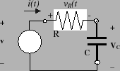
An ![]() circuit is a particularly simple network containing
a capacitor. The
circuit is a particularly simple network containing
a capacitor. The ![]() circuit consists of an independent
voltage source in series with a resistor,
circuit consists of an independent
voltage source in series with a resistor, ![]() , and a
capacitor
, and a
capacitor ![]() . The schematic diagram for this circuit is
shown in figure 2. Analyzing this
circuit means determining the voltage over the capacitor,
. The schematic diagram for this circuit is
shown in figure 2. Analyzing this
circuit means determining the voltage over the capacitor,
![]() , (as a function of time). The exact solution, of
course, depends on two things. These two things are the
initial voltage over the capacitor,
, (as a function of time). The exact solution, of
course, depends on two things. These two things are the
initial voltage over the capacitor, ![]() , and the input
voltage,
, and the input
voltage, ![]() , generated by the independent source. In
the remainder of this section we state two specific
solutions known as the natural response and step
response. The derivation of these particular response
equations is done in the lecture component of the course.
, generated by the independent source. In
the remainder of this section we state two specific
solutions known as the natural response and step
response. The derivation of these particular response
equations is done in the lecture component of the course.
Natural Response: The first specific solution we'll
consider is the voltage over the capacitor under the
assumption that the capacitor's initial voltage is ![]() and the applied input voltage is zero (i.e.,
and the applied input voltage is zero (i.e., ![]() for
all
for
all ![]() ). This particular solution is called the
natural response of the
). This particular solution is called the
natural response of the ![]() circuit and it can be
shown to have the form
circuit and it can be
shown to have the form
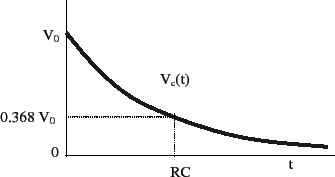
It is valuable to plot the general shape of the natural
response in equation 1. Note that the
voltage has a time dependency that is an exponential
function of time. This exponential function, ![]() has a negative exponent so that as
has a negative exponent so that as ![]() increases, the
function's value decreases in a monotone (non-increasing)
manner to zero. In other words, if we consider
increases, the
function's value decreases in a monotone (non-increasing)
manner to zero. In other words, if we consider
![]() for
for ![]() , we expect it to start
(at time 0) at the voltage
, we expect it to start
(at time 0) at the voltage ![]() and then to taper off to
zero as
and then to taper off to
zero as ![]() increases. This particular relationship is
shown in figure 3.
increases. This particular relationship is
shown in figure 3.
Note that the expression, ![]() , has units of time. We
generally refer to
, has units of time. We
generally refer to ![]() as the time constant of the
circuit. In fact, at time
as the time constant of the
circuit. In fact, at time ![]() , we know that the
voltage is
, we know that the
voltage is
![]() . This means that after one "time constant",
the initial voltage on the capacitor has decayed to about
one third of its initial value. After three time
constants, we expect
. This means that after one "time constant",
the initial voltage on the capacitor has decayed to about
one third of its initial value. After three time
constants, we expect
![]() . This is, of course, a very small number and it
means that after 4-5 time constants, the voltage over the
capacitor is essentially zero. The time it takes to
finish discharging the capacitor is determined by our
choice for the resistors
. This is, of course, a very small number and it
means that after 4-5 time constants, the voltage over the
capacitor is essentially zero. The time it takes to
finish discharging the capacitor is determined by our
choice for the resistors ![]() and
and ![]() . In other words, the
discharge time for the capacitor is determined by the
RC constant of our circuit.
. In other words, the
discharge time for the capacitor is determined by the
RC constant of our circuit.
Standard capacitor values are on the order of
![]() F (a large capacitor) to pico-farads. If we were to
use a 1 k-ohm resistor in series with a 1
F (a large capacitor) to pico-farads. If we were to
use a 1 k-ohm resistor in series with a 1 ![]() F capacitor,
the RC constant would be
F capacitor,
the RC constant would be
![]() m-sec. In this case, our source-free circuit would
discharge the capacitor in about 4-5 milli-seconds. If we
were to use an even smaller capacitor, let's say about 100
pico-farad, then this discharge time would be even shorter.
In particular, for a 100 pico-farad capacitor in series
with a 1 k-ohm resistor, we would expect a time constant of
m-sec. In this case, our source-free circuit would
discharge the capacitor in about 4-5 milli-seconds. If we
were to use an even smaller capacitor, let's say about 100
pico-farad, then this discharge time would be even shorter.
In particular, for a 100 pico-farad capacitor in series
with a 1 k-ohm resistor, we would expect a time constant of
![]() sec. This
is one tenth of a micro-second. So in this case we would
discharge a capacitor in about half a micro-second, a very
very short time interval.
sec. This
is one tenth of a micro-second. So in this case we would
discharge a capacitor in about half a micro-second, a very
very short time interval.
Step Response: The second specific solution we'll
consider is the voltage over the capacitor under the
assumption that the capacitor's initial voltage is ![]() and the applied input voltage is a step function of
magnitude
and the applied input voltage is a step function of
magnitude ![]() . In other words,
. In other words,
Let's assume that ![]() so that the capacitor is
initially uncharged. In this case the step response takes
the following simplified form,
so that the capacitor is
initially uncharged. In this case the step response takes
the following simplified form,
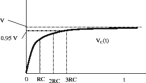
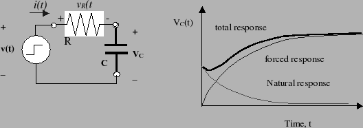
If we do not neglect the initial charge on the capacitor, then the circuit's response is given by equation 2. Notice that this equation is simply the sum of equation 3 and the natural response in equation 1. So we can simply sum the two responses shown in figure 3 and 4 to obtain a plot of the system's total response.
Figure 5 illustrates how these
individual parts of the response are combined to form the
total response. One of the lighter lines represents the
forced response to a step input. The other decreasing light
line represents the natural response to an initial voltage
on the capacitor. The total response is simply obtained by
taking their sum which is shown by the dark trace in figure
5. What we see in this figure is that
as time goes to infinity, the initial charge on the
capacitor dies away and the total response converges to the
steady state voltage ![]() .
.