Introduction
Technology Organizations Pros and
Cons FAQs Resources
Technology
![]() Technologies and Standard
Outlooks
Technologies and Standard
Outlooks
![]() Introduction to HiperLAN 1
System
Introduction to HiperLAN 1
System
![]() Channel Access and Control (CAC)
Channel Access and Control (CAC)
![]() Introduction to HiperLAN 2 System
Introduction to HiperLAN 2 System
![]() Data Link Control Layer & Convergence
Layer
Data Link Control Layer & Convergence
Layer
![]() Applications and Performance of
HiperLAN 2
Applications and Performance of
HiperLAN 2
Technologies and Standards Outlooks
The
wireless LAN arena is filled with a variety of different standards. These
include:
- different frequency bands
- different frequency ranges
- different modulation schemes
- different features.
Table
1 summarizes the key elements of each technology standard, specifically noting those
features and characteristics that differentiate them from each other.
The
single primary differentiating factor in wireless networking is the frequency
band of operation. Currently, the dominant standards and technologies operate
in one of two bands:
The 2.4GHz Wireless Networking Standards &
Industry Groups
The 5GHz Wireless Networking Standards &
Industry Groups
Within
these two bands differences and features may abound, however the frequency band
of operation is the first point that solidly groups the different technologies.
The
2.4GHz Wireless Networking Standards & Industry groups
IEEE 802.11
IEEE 802.11 refers to the standard family developed by the Institute of
Electrical and Electronics Engineering (IEEE) . Ratified in June 1997,
IEEE802.11 specifies the physical (PHY) and media access control (MAC) protocol
layers within a wireless LAN. Three physical layers are defined, one for each
wireless implementation method originally envisaged by the standard:
![]() Direct
Sequence (DS)
Direct
Sequence (DS)
![]() Frequency
Hoping (FH)
Frequency
Hoping (FH)
![]() Infrared
(IR).
Infrared
(IR).
The
MAC layer is the same for all three methods employing a scheme called
carrier-sense multiple access/collision avoidance (CSMA/CA).
IEEE 802.11b
IEEE802.11b, the first extension of the IEEE 802.11 standard, was ratified
during 1999 and employs a modulation scheme called complementary code keying
(CCK). Operating in the 2.4GHz band, CCK is capable of data rates from 1-11Mbps
for Direct Sequence (DS) systems.
SWAP (HomeRF)
HomeRF, which draws on well-proven Digital European Cordless Telephone (DECT)
voice technology and the networking algorithms of the IEEE
802.11 standards family, was designed specifically.
HomeRF's
Shared Wireless Access Protocol (SWAP) promises price points similar to those
of Bluetooth with a 1Mbps data rate in addition to digital voice transmission.
OpenAir
The OpenAir industry specification is a 2.4GHz FH spread-spectrum architecture
based on Proxim's RangeLAN2 radio technology. Products based on OpenAir can
support data rates up to 1.6Mbps at a range of 45-50 meters.
Bluetooth
Bluetooth is envisioned as a short-range wireless connectivity technology to
synchronize data among PCs, handled devices, and mobile phones, thereby
creating networks sometimes called personal area networks or PANs. Bluetooth
does not support a true network topology for employing a point-to-point master
/ slave configuration rather than a true peer-to-peer network protocol for data
exchange. With a peak data rate around 2Mbps, Bluetooth is not seen as a
serious contender for home networking systems.
WECA
In August 1999, key proponents of Direct Sequence (DS) technology, including
3COM, Aironet, Intersil, Lucent, Nokia, and Symbol, formed the Wireless
Ethernet Compatibility Alliance (WECA) . WECA is an organization established
for the purpose of certifying the interoperability of IEEE802.11b products that
use this modulation scheme providing a Wi-Fi (wireless fidelity) seal of
approval. Since 2000, this industry group has supported the IEEE802.11 standard
committee, promoting IEEE802.11b as a global Wireless LAN standard across all
market segments. Today, the WECA industry group is composed of about 80 leading
companies from the personal computer, consumer electronics, peripherals,
communications, software, and semiconductor industries including industry
leaders such as 3COM, Cisco, COMPAQ, DELL, Intel, Lucent, Microsoft, Nokia, and
SONY.
HomeRF Working Group
The HomeRF Working Group Inc. (HRFWG) was formed to establish the mass
deployment of interoperable wireless networking devices for transmitting voice,
data and streaming media, and led the development of the HomeRF protocol. The
HRFWG, includes leading companies from the personal computer, consumer
electronics, peripherals, communications, software, and semiconductor industries.
Bluetooth Special Interest Group
The Bluetooth Special Interest Group (SIG) is driving the development and
marketing of Bluetooth wireless technology, and is comprised of leaders in the telecommunications,
computing, and networking industries. The Bluetooth SIG includes flagship
companies such as 3Com, Ericsson, IBM, Intel, Lucent, Microsoft, Motorola,
Nokia and Toshiba, as well as more than 2000 Adopter/Associate member
companies.
The
5GHz Wireless Networking Standards & Industry Groups
IEEE 802.11
IEEE 802.11 refers to the standard family developed by the Institute of
Electrical and Electronics Engineering (IEEE) . Ratified in June 1997,
IEEE802.11 specifies the physical (PHY) and media access control (MAC) protocol
layers within a wireless LAN. Three physical layers are defined, one for each
wireless implementation method originally envisaged by the standard:
![]() Direct
Sequence (DS)
Direct
Sequence (DS)
![]() Frequency
Hopping (FH)
Frequency
Hopping (FH)
![]() Infrared
(IR).
Infrared
(IR).
The
MAC layer is the same for all three methods employing a scheme called
carrier-sense multiple access/collision avoidance (CSMA/CA).
IEEE 802.11a
Approved in September 1999, the IEEE 802.11a standard is an extension of the
IEEE 802.11 standard designed to operate in the 5GHz band employing a
modulation scheme called Orthogonal Frequency Division Multiplexing (OFDM).
Data rates for IEEE 802.11a range from 6Mbps to 54Mbps and standard-compliant
products are required to transmit and receive at 6, 12, 24, and 36Mbps, with
optional extensions for 9, 18, 24, 48, and 54Mbps. IEEE 802.11a operates in ISM
specified frequency bands from 5.15GHz to 5.35Ghz and from 5.725GHz to 5.825GHz
spectrum(s). Additional extensions have been developed for both IEEE 802.11a
and / or IEEE 802.11b to address European regulation needs and advanced MAC
specifications such as authentication, Quality of Service (QoS), and encryption
(see Table 3).
HiperLAN 2
Broadband Radio Access Networks (BRAN) is a wireless networking project within
the European Telecommunications Standard Institute (ETSI) . ETSI-BRAN has
developed and ratified the HiperLAN wireless networking standards for the 5GHz
band. HiperLAN 2 was developed as part of a family of high-speed wireless
access standards able to connect to Universal Mobile Telecommunications Systems
(UMTS), ATM, and Internet Protocol (IP)-based networks. Like its American
companion IEEE 802.11a, HiperLAN 2 employs OFDM modulation technology
employing 455MHz of the Unlicensed National Information Infrastructure (U-NII)
frequency bands, from 5.150GHz to 5.350Ghz and from 5.470GHz to 5.725GHz. Data
rates for HiperLAN 2 range from 6Mbps to 54Mbps and standard-compliant products
are required to transmit and receive at 6, 12, 24, and 36Mbps, with optional
extensions for 9, 18, 27, and 54Mbps. The ETSI-BRAN project also developed
conformance test specifications for the core HiperLAN 2 standards, to assure
the interoperability of devices and products produced by different vendors.
H2GF
The ETSI-BRAN program is supported by the HiperLAN 2 Global Forum (H2GF), a
consortium of communications and information technology companies, headed by
Ericsson, that have joined together to ensure the completion of the HiperLAN 2
standard and to promote it on a worldwide level.
5GIAG
Microsoft, Compaq, and Intel formed the 5GHz Industry Advisory Group (5GIAG) in
June 2000, in order to drive industry convergence to a single global wireless
LAN standard that would result in a commercially attractive product for both
the home and corporate markets. After quickly realizing that a global standard
would not arise in the near future their efforts were focused on developing a
solution that would enable coexistence, and then interoperability, between the
two leading wireless LAN standards operating in the 5GHz band IEEE 802.11a and
HiperLAN 2.
WECA
In August 1999, key proponents of Direct Sequence (DS) technology, including
3COM, Aironet, Intersil, Lucent, Nokia, and Symbol, formed the Wireless
Ethernet Compatibility Alliance (WECA) . WECA is an organization established
for the purpose of certifying the interoperability of IEEE802.11b products that
use this modulation scheme providing a Wi-Fi (wireless fidelity) seal of
approval. Since 2000, this industry group has supported the IEEE802.11 standard
committee, promoting IEEE802.11b as a global Wireless LAN standard across all
market segments. Today, the WECA industry group is composed of about 80
companies from the personal computer, consumer electronics, peripherals,
communications, software, and semiconductor industries including industry
leaders such as 3COM, Cisco, COMPAQ, DELL, Intel, Lucent, Microsoft, Nokia, and
SONY.
Introduction to HiperLAN 1 System
HiperLAN
1 Reference Model
HiperLAN
1 defines Data Link Layer and Physical Layer. For Local Area Networks, Data
Link Layer is further divided into two sublayers: the Logical Link Control
(LLC) and the Medium Access Control (MAC). HiperLAN 1 only deals with MAC and
PHY.
Figure
1 - HiperLAN 1 Reference Model
An
intermediate layer, the Channel Access and Control (CAC) sublayer, is
introduced in the HiperLAN 1 architecture to deal with the channel access
signaling and protocol operation required supporting packet priority. A
pseudo-hierarchically independent access mechanism is achieved via active
signaling in a listen-before-talk access protocol. The Elimination-Yield Non-Preemptive
Multiple Access (EY-NPMA) mechanism codes priority level selection and
contention resolution into a single, variable length radio pulse preceding
packet data. EY-NPMA provides good residual collision rate performance for even
large numbers of simultaneous channel contenders.
Physical
Layer
RF
carriers
HiperLAN
1 uses the radio frequency band 5,150 MHz to 5,300 MHz. The following table
shows the nominal frequency of each carrier. It's required that all
transmissions shall be centered on one of the nominal carrier frequencies, and
all HiperLAN 1 equipments shall operate on all 5 channels.
|
Carrier number |
Center Frequency (MHz) |
|
0 |
5 176,4680 |
|
1 |
5 199,9974 |
|
2 |
5 223,5268 |
|
3 |
5 247,0562 |
|
4 |
5 270,5856 |
Table 4 - Nominal
carrier center frequencies
The
carriers numbered 0, 1 and 2 are designated the "default" carriers.
Clear
Channel Assessment (CCA)
The
HiperLAN 1 clear channel assessment scheme is based on the measurement of the received
signal strength only. A threshold is used for determining whether the channel
is busy or idle. Because the signal strength will vary with time, the
time-domain variation of the received signal strength is used for threshold
adaptation.
The
parameters for the measurement of signal strength are expressed as Signal Level
Number (SLN) (see the following graph). Because HiperLAN 1 signals is bursty in
nature and any interference will be of relatively constant power level, the
channel shall be considered to be idle when the received SLN is less than the
defer threshold value. In all other cases the channel shall be considered to be
busy. When the channel is busy, the threshold adaptation algorithm seeks to
raise the threshold to just above the level of any continuous signal on the
channel.
Figure
2 - Threshold Adaptation Algorithm
Modulation
For
HiperLAN 1, Gaussian Minimum Shift Keying (GMSK) is used as the high bit rate
modulation scheme to modulate a high rate transmission. GMSK is a Constant
Envelope modulation scheme, which means that the amplitude of the transmitted
signal is constant. This is important, because less stringent linearity can be
demanded of the RF amplifier, which in turn means the cost of the radio is
lower and, more importantly, the efficiency of the power amplifier (the ratio
of actual RF energy transmitted compared to the electrical energy consumed) is
quite good.
Frequency Shift Keying (FSK) is
used as the low bit rate modulation scheme to modulate a low rate transmission.
FSK is specified as follows: (fc is the center frequency.)
|
Bit value |
Nominal frequency |
|
0 |
f c - 368 kHz |
|
1 |
f c + 368 kHz |
Table 5 -
Nominal frequencies for FSK modulation
Channel
Access and Control (CAC)
The
CAC layer defines how a given channel access attempt will be made depending on
whether the channel is busy or idle, and at what priority level the attempt will
be made, if contention is necessary. It is the CAC layer which implements the
hierarchically independent, Non-pre-emptive Priority Multiple Access (NPMA)
mechanism on which most of the HiperLAN 1 advanced features are built.
A
transmission passes through three phases: the priorization phase, the
contention phase and the transmission phase. The transmission phase forms the
channel access cycles because during the transmission the medium is considered
free. The whole three phases forms a synchronized channel access cycle.
CAC
works in the following three steps:
1. During priorization phase, the data
transmissions with highest channel access priority are selected out. Channel
access priority is based on Packet Residual Lifetime and user priority.
2. In contention phase, CAC compete with any
other HiperLAN 1 CAC with same priority. CAC transmits a signal (the length of
signal is calculated based on geometric probability distribution). At the end
of transmission, the CAC listens to the channel. If another device is still
transmitting, it defers its transmission until the next channel access cycle.
Otherwise the CAC gains the channel and begins its transmission.
3. Transmit the data in the transmission
phase.
Figure
3 - Channel Access and Control
Due
to the non-pre-emptive requirement, a data transmission can compete the channel
only if it's ready at the beginning of a channel access cycle. Otherwise, it
should wait until the next channel access cycle.
Media
Access Control (MAC)
The
HiperLAN 1 MAC layer defines the various protocols that provide the HiperLAN 1
features of power conservation, security, and multi-hop routing, as well as the
data transfer service to the upper layers of protocols.
Topology
HiperLAN
1 support both infrastructure and ad-hoc topology. In infrastructure topology,
each HiperLAN 1 device will select one and only one neighbor as Forwarder and
transmits all traffic to the Forwarder. In ad-hoc topology, there is no such
controller, every device can communicate directly with each other.
Priority
In
IEEE 802.11, Priority is embedded in Inter-Frame Space, thus the priority is
fixed. HiperLAN 1 assigns channel access priorities dynamically to the packets.
HiperLAN 1 uses the following two parameters to calculate the priority:
Packet Lifetime
User Priority
Since
Packet Lifetime is updated constantly, the priority will increase with time.
When it's getting near to the packet expiration, its priority will increase to
the highest point.
Multi-Hop
Routing
HiperLAN
1 uses "Hello" message to do Neighborhood Discovery. Each device will
periodically send a "Hello" packet to its neighbors. One type of
"Hello" packet will carry a list of sender's neighbors.
Forwarder
constructs the whole map of the HiperLAN 1 using this information. Then it can
decide which device will be the next hop for a given destination and it can
forward packets from on hop to another.
Figure
4 - Multi-Hop Routing
Power
Saving
In
HiperLAN 1, mobile devices can agree upon awake patterns (e.g., periodic
wake-ups to receive data), some nodes in the networks must be able to
buffer data for sleeping devices and to forward them at the right time.
The
power conservation functions are performed by two roles: p-supporter and
p-saver. P-saver is the power-conserving device, and p-supporter is the
neighbor of the p-saver who defers transmission of packets to the p-saver.
P-saver will broadcast to its neighbors the pattern when it will sleep and when
it will wake. Using such information, p-supporter can know when to transmit the
buffered packets to p-saver.
In this mechanism, the periodicity and length
of the sleep/wake intervals can be selected to match different application
needs. So p-saver can decide how to make best use of its power.
Products
Proxim's
High Speed RangeLAN5 product family
- Offering 24 Mbps data rates
- Operating in the 5 GHz band
- Guaranteed Quality of Service (QoS) for
Multimedia Applications
- Independent Channels for Increased Aggregate
Throughput
RadioLAN
provides a set of products for indoor wireless communication
- Offering 10Mbps
- Operating in the 5 GHz band
- Peer-to-peer
Topology
Introduction to HiperLAN 2 System
For
a more detailed description, please refer to:
http://www.hiperlan2.com/presdocs/site/whitepaper.pdf
http://www.ericsson.com/wlan/pdf/h2_ereview2.pdf
http://www.etsi.org/getastandard/home.htm,
ETSI’s up-to-date standards’ specification
HiperLAN
2 Reference Model
Like
other wireless LAN technologies, HiperLAN 2 lets mobile terminals connect to
access points that bridge traffic to wired networks. It is also possible for
mobile nodes to communicate directly with each other, though in practical
deployments this will likely be the exception.
HiperLAN
2 works as a seamless extension of other networks, so wired network nodes see
HiperLAN 2 nodes as other network nodes. All common networking protocols at
layer 3 (IP, IPX, and AppleTalk, for example) will operate over HiperLAN 2,
permitting all common network-based applications to operate.
As
Figure 5 shows, HiperLAN 2 defines a Physical layer and a Data link control
layer. Above these is a Convergence layer that accepts packets or cells from
existing networking systems and formats them for delivery over the wireless
medium.
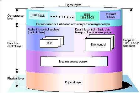
Figure
5 - HiperLAN 2 Reference Model
Physical
Layer
The
first unique aspect of HiperLAN 2 is OFDM. Though OFDM has been used before—in
the European Digital Audio Broadcast (DAB) standard and in Asymmetric Digital
Subscriber Lines (ADSLs) — it has never before appeared in a wireless LAN
standard.
OFDM
is extremely effective in a time-dispersive environment where signals can take
many paths to reach their destinations, resulting in variable time delays. At
high data rates, these time delays can reach a significant proportion of the
transmitted symbol (a modulated waveform), resulting in one symbol interfering
with the next in what is called “intersymbol interference.” OFDM combats this
by dividing a radio channel into multiple subcarriers and transmitting data in
parallel on them. The aggregate throughput ends up being the same, but the data
rate of each subcarrier is much lower, making each symbol longer — thus
practically eliminating the effect of the variable time delays. However, OFDM
demands extremely linear power amplifiers, which increase the cost of the
radio. Consequently, HiperLAN 2 products will likely cost more than lower-speed
alternatives.
In
the spectrum allocation for Europe, HiperLAN 2 channels will be spaced 20MHz apart
— for a total of 19 channels. Each channel will be divided into 52 subcarriers,
with 48 for data and four as pilots that provide synchronization.
Synchronization enables coherent (in-phase) demodulation. Through digital
signal processing, subchannels are divided through mathematical processing,
rather than in the analog domain.
OFDM
by itself does not fully describe the Physical layer. There is also the
question of how data is encoded and the type of modulation used in each
subchannel. Encoding involves the serial sequencing of data, as well as Forward
Error Correction (FEC). Most lower-speed wireless LANs do not employ FEC, but
HiperLAN 2 provides multiple levels, each capable of protecting against a
certain percentage of bit errors.
HiperLAN
2 also employs multiple types of modulation. By dynamically adapting the FEC
and modulation according to varying conditions, HiperLAN 2 can transmit at
higher data rates with a strong signal relative to noise; it can also transmit
data at lower throughputs under adverse conditions.
Data
Link Control Layer & Convergence Layer
The
next layer is the Data-link layer. In HiperLAN 2, the Data-link layer is
connection-oriented, which differentiates it from other wireless LAN
technologies. Before a mobile terminal transmits data, the Data-link layer
communicates with the access point in what is called the signaling plane to set
up a temporary connection. This connection approach permits the negotiation of
QoS parameters like bandwidth and delay requirements. It also assures that
other terminals will not interfere with the subsequent transmission.
By
contrast, a mobile terminal that conforms to the IEEE 802.11 standards will
communicate when the radio channel becomes available, and it may experience
packet collisions from other terminals. It should be mentioned, however, that
IEEE 802.11 does provide a separate mechanism for synchronous applications like
voice.
HiperLAN
2 implements QoS through time slots. QoS parameters include bandwidth, bit
error rate, latency, and jitter. The original request by a mobile terminal to
send data uses specific time slots that are allocated for random access.
Collisions from other mobile terminals can occur in this random-access channel,
but since these messages are brief, this is not a problem.
The
access point grants access by allocating specific time slots for a specific
duration in what are called transport channels. The mobile terminal then sends
data without interruption from other mobile terminals operating on that
frequency. A control channel provides feedback to the sender, indicating
whether data was received in error and whether it needs to be retransmitted.
Above
the Data-link layer is the Convergence layer, which responds to service
requests from higher layers and formats data as required. This layer supports
both packet-based (Ethernet) and cell-based (ATM) communications. When
implemented for Ethernet, the Convergence layer preserves Ethernet frames and
uses either conventional best-effort communications or the IEEE 802.1p priority
scheme.
HiperLAN
2 also comes with Automatic Frequency Allocation (AFA). To provide continuous
coverage, access points need to have overlapping coverage areas. Coverage
typically extends 30 meters indoor and 150 meters in unobstructed environments.
Access points monitor the HiperLAN radio channels around them and automatically
select an unused channel. This eliminates the need for frequency planning and
makes deployment relatively straightforward.
When
a mobile terminal roams from the coverage area of one access point to another,
it initiates a handoff to the new access point after detecting a better signal
on another radio channel. The new access point obtains details of the mobile
terminal’s connection from the old access point, and communications continue
smoothly.
HiperLAN
2 secures communications for a mobile terminal, creating a session (called an
association) with an access point by first using a Diffie Hellman key exchange
to negotiate a secret session key, then a mutual authentication process via
either a secret key or a public key, if a PKI is available. Data traffic is
encrypted using DES or Triple DES.
With
these security mechanisms, communication over HiperLAN 2 should be as secure—if
not more so—as over a wired LAN.
Applications and Performance of HiperLAN 2 (this
part is taken from H2GF white paper)
Example applications
Corporate
LAN
Figure
6 below shows an example of a corporate network built around Ethernet LAN and IP
routers. A HiperLAN 2 network is used as the last segment between the MTs and
the network/LAN. The HiperLAN 2 network supports mobility within the same
LAN/subnet. Moving between subnets implies IP mobility, which must be taken
care of on a layer above HiperLAN 2.
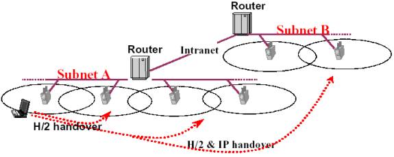
Figure
6 - HiperLAN 2 used in a corporate network
Hot
spots
HiperLAN
2 networks can be deployed at hot spot areas, e.g. airports, hotels, etc, to
enable an easy way of offering remote access and Internet services to business
people. An access server to which the HiperLAN 2 network is connected can route
a connection request for a point-to-point connection (PPP) over a tunnel either
to the corporate network (possibly via a preferred ISP) or perhaps to an ISP
for Internet access.
Access
to 3rd generation cellular network
HiperLAN
2 can be used as an alternative access technology to a 3rd generation cellular
network. One may think of the possibility to cover hot spots and city areas
with HiperLAN 2 and the wide area with WCDMA technology. In this way, a user
can benefit from a high-performance network wherever it is feasible to deploy
HiperLAN 2 and use W-CDMA elsewhere. The core network sees to that the user is
automatically and seamlessly handed over between the two types of access
networks as the user moves between them.
Home
network
Another
example of HiperLAN 2 is to use the technology in a home environment to create
a wireless infrastructure for home devices, e.g. home PCs, VCRs, cameras,
printers, etc. The high throughput and QoS features of HiperLAN 2 support the
transmission of video streams in conjunction with the data comm. applications.
The AP may in this case include an “uplink” to the public network, e.g. an ADSL
or cable modem.
Performance
The
performance in terms of user throughput and delay depends upon a number of
factors, such as the available number of frequencies, the propagation
conditions in the building and the presence of interference, e.g. another
HiperLAN 2 system in the close vicinity.
The
performance for two "typical" environments have been evaluated, a
five storey office building and an open exhibition hall. The office building
includes attenuation from walls and floors, and the exhibition hall consists
only of line of sight propagation. The performance with link adaptation is
compared with a reference case with a fixed PHY mode (mode 4. The obtained
performance results can be compared to the ETSI requirement of 20 Mbps average
system throughput and 25 Mbps peak data rate (input to the physical layer)).
The system throughput is calculated as the mean throughput for all users.
In
the office environment the reference case with a fixed PHY mode and omni
antennas does not provide the required 20 Mbps system throughput. However, when
link adaptation is used, the throughput is close to 35 Mbps, i.e. well above
the requirement.
In
the exhibition hall, the throughput also exceeds the required 20 Mbps when link
adaptation is used. It can be seen that the use of multi beam antennas
increases the throughput even further. Given that the exhibition hall scenario
is an extreme case, e.g. with LOS propagation and 100% system load, the
requirements are expected to be fulfilled for most scenarios and traffic mixes.
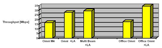
Figure
7 – System Throughput