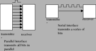
A serial interface is a communication interface between two digital systems that transmits data as a series of voltage pulses down a wire. A "1" is represented by a high logical voltage and a "0" is represented by a low logical voltage. Essentially, the serial interface encodes the bits of a binary number by their "temporal" location on a wire rather than their "spatial" location within a set of wires. Encoding data bits by their "spatial" location is referred to as a parallel interface and encoding bits by their "temporal" location is referred to as a serial interface. Figure 3 graphically illustrates the difference between these two communication methods.
A key issue with a serial interface is knowing where the data is on the wire. As an example, let's assume that the wire is initially at a low logical level. We'll refer to this as the idle channel condition. If we now transmit a string of zeros down the wire, how can we distinguish between the string of zeros and the idle channel condition?
The answer to our dilemma lies in creating a protocol. A protocol is an agreement between two parties about how the two parties should behave. A communication protocol is a protocol about how two parties should speak to each other. Serial communication protocols assume that bits are transmitted in series down a single channel. A serial protocol has to address the following issues
OutString to write out
characters to the PC's terminal window. The synchronous
serial link (SPI) is used when you transmit data between
devices that may not have an internal clock. The SPI
interface is what you'll use in this lab because the
parallel-to-serial shift register you're using has no
internal clock.
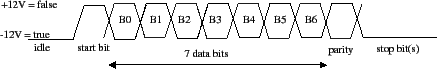
Asynchronous (SCI) Serial Interface: In an asynchronous serial interface (SCI), data is transmitted in well-defined frames. A frame is a complete and nondivisible packet of bits. The frame includes both information (e.g., data) and overhead (e.g. control bits). In asynchronous serial protocols the frame often consists of a single start bit, seven or eight data bits, parity bits, and sometimes a stop bit. A representative timing diagram for a frame that might be used by an SCI interface is shown in figure 4. In this figure, the frame has one start bit, seven data bits, one parity bit, and one stop bit. Most of the bits in this frame are self-explanatory. The start bit is used to signal the beginning of a frame and the stop bit signals the end of the frame. The parity bit is a special bit that is used to detect transmission errors.
In an asynchronous serial interface, the reading of the data line is initiated by detecting the start bit. Upon detecting the start bit, the receiver then begins reading the "data" bits from the line at regular intervals determined by the receiver's clock. This means, of course, that the transmitter and receiver must have a prior agreement on the rate at which data is to be transmitted.
The issue of "when" to look for data bits in the frame must be agreed upon prior to establishing the link. Asynchronous serial protocols usually require that information bits be transmitted at regular time intervals. For instance if we have a 2400 kbaud modem, then both receiver and transmitter know that they should look for information bits arriving at a rate of 2400 thousand bits per second.
The SCI interface is said to be asynchronous because both devices do not need to synchronize their clocks before communicating. The receiver simply waits for the start bit and then beginnings reading the data line at the agreed upon baud rate. What this means is that the transmitter can transmit a frame without waiting for the receiver to explicitly synchronize to the transmitter's clock. In other words the receiver can receive data in an asynchronous manner from the transmitter.
Synchronous Serial Interface: In a synchronous serial interface, the receiver has no internal clock. This means that the receiver cannot independently synchronize its reading of the data line with the transmitter's transmission rate. The receiver needs some help and that help comes in the form of a clock signal that is shared by the transmitter and receiver. The clock signal acts a control line that tells the receiver when to read from the data line. What this means is that the transmitter and receiver must synchronize their access to the data line in order to successfully transmit data.
SPI interfaces are used when the micro-controller has to transmit data to a device without an internal clock. This is precisely the situation that occurs when we use the MicroStamp11 to transmit data to the shift-register. The MicroStamp11 has an internal clock, but the shift-register has no clock. We usually think of the device with the clock as a master and the other device as a slave. So in our case the MicroStamp11 is the master and the shift-register is the slave. Typically the slave uses the master's clock to shift data into or out of the slave. This means that the SPI serial channel needs a minimum of two lines. The primary two lines are somtimes referred to as the data and clock lines. The data line actually has the data bits and the clock line carries clock pulses telling the slave when to read/write the data bits. The value of this approach is that the slave can be a rather simple, inexpensive, and low power device. The disadvantage is that the SPI interface will need control lines in addition to the data line. The SCI interface, on the other hand, only needs a single data line. In this lab, the SPI interface will need three lines (see figure 1); one data line, one clock line, and an additional line that is used to control the internal state of the shift register. Details on how to use the MicroStamp11's SPI subsystem are discussed in the next subsection.