In the LED display you designed earlier, each LED is controlled by a separate I/O pin. Since our display has seven segments, this means that seven of the MicroStamp11's output lines are needed to drive the display. This is a problem because the MicroStamp11 only has eleven output lines. So our earlier design uses nearly all of the output lines to drive the display, thereby reducing the ability of the MicroStamp11 to interact with other peripheral devices.
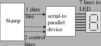
One way to reduce the required number of output lines is to use a serial interface between the MicroStamp11 and the display. In a serial interface, the Micro-controllers sends a "series" of pulses, one after the other, down a single wire. Each of these pulses represents the value that one of the LED segments must take. A serial-to-parallel device called a shift register is used to transform this series of pulses into a constant signal on seven separate lines. We still have seven wires going to the LED display, but in this case, we only need one wire (plus perhaps a couple of extra control lines) between the MicroStamp11 and the serial-to-parallel device.
The picture in figure 1 illustrates the proposed connections between the MicroStamp11 and the serial-to-parallel interface. The lab uses the MicroStamp11's synchronous serial (SPI) subsystem to drive a shift register that will serve as our serial-to-parallel device.
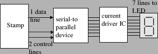
This lab also introduces another enhancement to the LED display. The shift register used in this lab is unable to source a great deal of current. So if we were to drive the LED display directly from the shift register (as shown in figure 1), then the lit LEDs would be very dim. In order to brighten up the display, we need to drive the LEDs with more current. In this lab, we will do this by using a special driver integrated circuit that implements an array of transistor current drivers. The driver IC will be connected in series between the shift register and the LED display as shown in figure 2.